
This is the final part of a four-part post detailing the design, manufacture, and programming of a reflow oven based on the Panasonic NT-GT1, 9-liter, 1200W toaster oven:
- 1 (Oven hardware)
- 2 (Controller hardware)
- 3 (Manufacturing)
- 4 (Controller software)
Continuing on from the prior posts on the controller hardware and manufacturing, the device needs software.
Since the core function of the oven is to run the reflow profile, let’s spend some time there.
Precise Temperature Control
The classic algorithm to control an oven like this is PID.
What is a PID controller?
PID is a type of feedback control system that is used to automatically achieve a desired setpoint of some type of process variable by controlling an output level.
This variable might be the speed of a motor, the pressure of a container in a factory, the flow rate in a dam, etc. The corresponding output in these examples could be the power delivered to the motor, the opening amount of the inlet valve to the container, and the height of the dam gate controlling the water flow.
The controller is told the current level of the process variable and the desired level (setpoint), and then calculates the appropriate output level to achieve the desired setpoint.
The key feature of PID control is that it has memory. That is, it doesn’t only look at the difference between the current process variable level and the desired level (i.e. the error), but also takes into account prior errors, and the rate of change of the error (i.e. if it’s getting better or worse).
- P - Set the output based on the current error
- I - Set the output based on the sum of prior errors
- D - Set the output based on whether the error is increasing or decreasing
In our case:
process variable= oven temperaturesetpoint= target temperature, andoutput= power delivered to the elements.
Sometimes it actually is simpler to write your own
There are many open source C/C++ PID algorithms available, but after spending some time with a few, I was unable to obtain satisfactory results. It’s certainly possible to analyze and modify them, but for such a simple algorithm, I found it far quicker and easier to just write my own basic controller. Tuning your own implementation is also easier since it’s well understood.
I first tuned the bake function, which proved relatively painless. A PID algorithm is well suited to this task, and gave excellent results with a very stable temperature.
Reflow on the other hand, was more challenging.
A PID algorithm based on temperature alone was not good enough
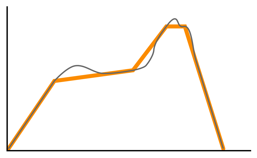
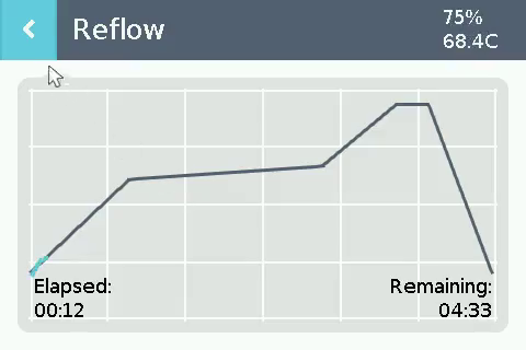
The combination of the thermal mass off the elements/oven and the sharp changes in dT/dS (i.e. temperature slope) present in typical reflow profile rendered the standard PID implementation inadequate here.
The different reflow stages mean that without some sort of look-ahead mechanism, it’s not possible to avoid something like this happening:
The thermal mass of the oven means that even with perfect tuning, the algorithm will always be trying to catch up.
The two ideas I had to fix this were:
- Use a look-ahead for the target setpoint (i.e. target the temperature we want in X seconds).
- Use dT/dS as the process variable.
After some initial testing, I settled on a combination of the two:
current_dtds = (current_temp - prior_temp) / lookback_period
target_dtds = (future_profile_temp - current_temp) / lookahead_period
new_output_pwr = computePid(target_dtds, current_dtds)
For baking, only the temperature PID is used. For reflow, the above combination is used.
Drivers
ILI9481 display and FSMC controller
The ILI9481 conforms to the MIPI-DBI (V2) bus and the MIPI DCS command set standards. I have no experience with these, but figured writing a reusable MIPI driver was a better time investment than something ILI9481 specific. Many devices support the MIPI standards.
FSMC (Flexible Static Memory Controller)
I chose the specific MCU model due to its FSMC support. The FSMC controller is designed to perform large data transfers over an 8/16/32-bit bus quickly and is intended for use with external SRAM, Flash, and LCDs.
Once configured, the controller handles all of the timing/waveform/addressing requirements of the connected device, allowing the code to simply specify a source address and length, and hit go. When paired with the DMA controller, the CPU is free to perform other tasks during the transfer, with completion notification via interrupt.
A 38kb buffer for a 300kb display
A full screen buffer for the display would require 300kb (480x320x16-bit). Our MCU has 64kb of SRAM. The actual drawing buffer used is 37.5kb, or 1/8 of the display.
The graphics library used for this project (LVGL - see below) supports partial buffers by writing a full frame in multiple passes. The code draws the top 1/8 of the screen in the buffer, copies it to the display via FSMC, then the second 1/8 and so on. Performance is more than adequate.
LCD backlight
The backlight LED is driven by the STM32 PWM timer output (via a switching FET). Frequency is set to 50kHz to avoid any audio interference on the amplifier/speaker.
Touch screen
I plan to use capacitive touch screens in future, so I didn’t spend much time making the touch screen code reusable. As such, it’s STM32 specific. It uses basic digital GPIO and analog inputs per the process outlined in the controller hardware post.
MAX31856 thermocouple decoder
I wrote a basic driver for the decoder and subsequently found a bunch already available online…
Oven SSR
As with the LED backlight, the STM32 PWM timer is used to vary the power level of the oven via a switching FET connected to the oven power SSR. The SSR does zero-crossing, so the minimum “on” time is half a mains cycle:
mcu_freq       = 72'000'000
mains_freq     = 60 Hz
crossing_freq  = mains_freq * 2
power_steps    = 100
tim_resolution = mcu_freq / crossing_freq
tim_period     = time_resolution * power_steps
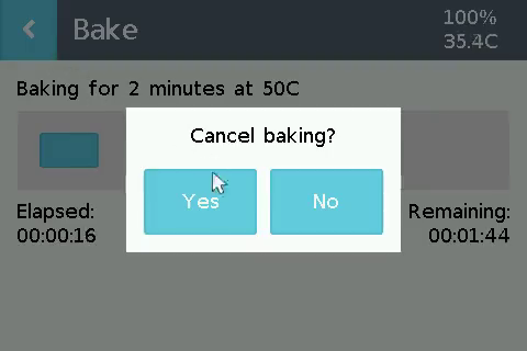
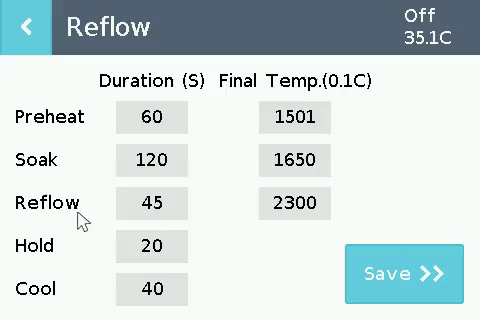
User Interface
For basic, output only projects, I use my own primitive/text drawing library, but since this project uses a touch screen, it made more sense to use something with input capabilities.
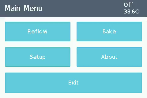
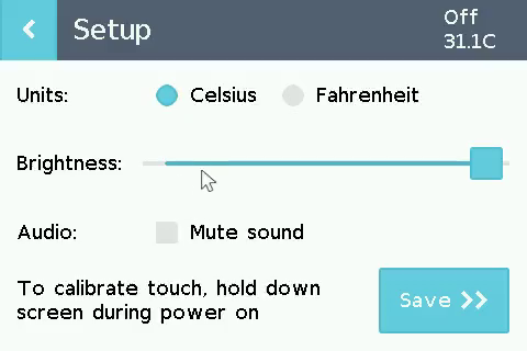
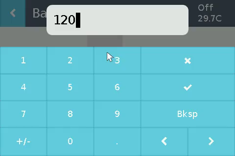
The LVGL-based user interface:
LVGL is an excellent embedded GUI library
I’ve evaluated a few different open source libs in the past, and haven’t found any that I prefer over LittlevGL (now LVGL).
It’s actively developed with excellent documentation and the primary developer is extremely responsive and accommodating. It’s a C library, but integrates easily with C++, and consumes minimal resources (although that seems to be changing in more recent versions).
Two simple wrappers (4 functions total) are all that are required to integrate the library with the TFT LCD and touch screen drivers described above.
The UI code is a bit of a mess, but it works well and shouldn’t ever require modifications.
Doing away with piezo beeps
With dual DACs on board and plenty of flash to spare, a speaker was incorporated into the design for more pleasant audio feedback.
I hadn’t used the STM32 DACs before, but the below application note was very helpful in explaining their use:
AN3126 - Audio and waveform generation using the DAC in STM32 microcontrollers
The duration of audio played on the completion of a bake/reflow operation is quite long and can repeat, so the code uses the STM DMA peripheral to avoid complex handling code/locking up the UI.
Libraries and Language
C++ as usual
There’s no shortage of C vs C++ arguments in the embedded and systems programming space. I use C++* mostly because I find it easier to structure and read my code, and prefer modern C++ for its stricter typing, better static analysis and metaprogramming features, and zero-overhead abstraction capabilities.
In particular, the ability to construct complex data structures at compile time with constexpr/consteval and store them in .rodata can save a lot of RAM.
* The code in this type of project is more like C with classes plus several C++ language features. Much of C++’s more advanced and helpful memory features go unused, given that everything is statically allocated.
That said, there are several things that I dislike. Specifically, I find compile-time polymorphism to be a mess. Templates with Concepts accomplish the task, but the syntax feels clumsy, they don’t auto-document well, and the template parameters infect everything that comes into contact with them. “Abstract” base classes as interfaces can also work, where the compiler is able to remove the abstraction, but that’s not always the case.
It’s quite possible that I just don’t know the language well enough (I definitely don’t), but I don’t think I’m missing anything fundamental. I’d like to try out Rust on a project at some point, but will wait for it to become a bit more developed in the embedded space.
Avoiding the STM32 HAL
I have used the STM32 HAL libraries in projects, but usually don’t anymore. They work pretty well in general and sometimes save a lot of time, but in my experience, they occasionally fail for some obscure reason and the time spent getting to the bottom of the problem more than offsets the time saved. That’s just my experience though, plenty of people use and like them. They’ve also probably improved a lot since I last used them.
I try to write generically where it’s possible to do so without introducing too much overhead, and put the code in a repo called Libpekin, which I then use in other projects. It’s split into a platform independent module (utilities, drivers etc.) and hardware specific modules with code for peripherals etc..
There are innumerable other high quality libraries and OSs available, but it’s always a tradeoff between time spent learning and debugging with external libraries and writing them yourself. For applications with more advanced requirements (wireless stacks etc.), vendor drivers and an OS makes sense and I would not recommend writing your own.
The Final Firmware
The final build is ~193kb (63kb audio samples, 22kb fonts) using 61kb of SRAM. ~37/18kb of that is the display buffer/LVGL working memory. See Github for the full firmware source and PCB design files.