
This is the first part of a four-part post detailing the design, manufacture, and programming of a reflow oven based on the Panasonic NT-GT1, 9-liter, 1200W toaster oven:
- 1 (Oven hardware)
- 2 (Controller hardware)
- 3 (Manufacturing)
- 4 (Controller software)
After reflowing for some time with hot air and saucepans, I’ve decided it’s time to build a dedicated reflow oven. There are tons of DIY reflow oven projects out there, but I decided to design and build my own (see NIH syndrome) for the fun of it.
Requirements for the oven itself are: cheap, high power, top and bottom quartz elements, small volume, and a roomy control area to house the updated electronics. In this part of the world, the Panasonic NT-GT1, 9 liter, 1200W oven is available for around US$35 and suits the application well.
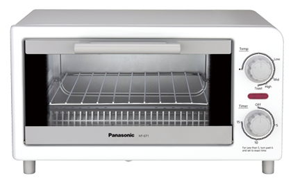
Panasonic NT-GT1 Toaster Oven
Accurately measuring the PCB temperature
It’s the temperature of the PCB and components that is of interest during reflow. Commercial ovens may use multiple temperature probes connected to the target PCB and components in various locations to develop a custom reflow profile for every specific application. This is not practical here, and we’ll be using a single thermocouple to estimate the board temperature.
A thermocouple is a type of sensor that leverages the thermoelectric effect to measure temperature. You can read more about thermocouples here.
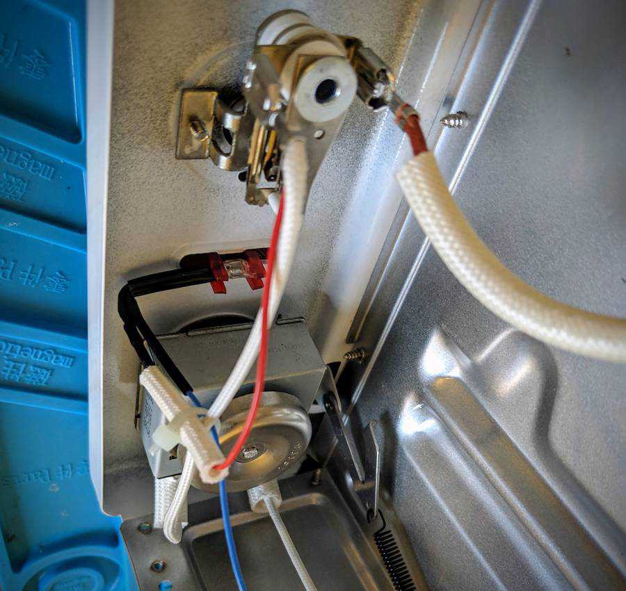
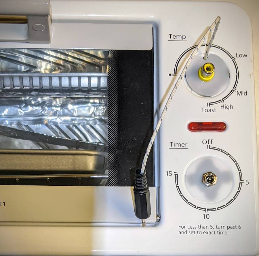
The thermocouple is placed well away from the walls, directly above the PCB tray to ensure as accurate an estimation as possible. During reflow, it can be tilted down to physically contact the target PCB.
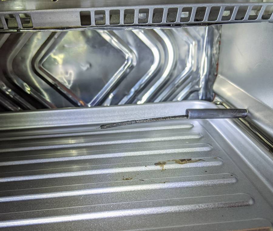
K-type thermocouple used to estimate PCB temperature
Improving the ramp rate
To maximize the lifespan of reflowed boards and reduce the possibility of component and soldering failures, the manufacturers’ profiles need to be followed closely. This requires the ability to ramp (and cool) quickly when required.
In order to avoid spending too much time at high temperature, an instantaneous temperature slope of at least 2°C/second is required. Plenty of people successfully reflow at slower rates, but the point of this project is take a step up from “good enough” methods.
Testing the stock performance
The stock oven cannot heat this quickly (see chart below). There are three things that can be done to improve the ramp rate:
-
Increase the power -> add elements.
-
Reduce the specific heat capacity of the oven -> get rid of stuff.
-
Reduce the conduction/convection losses -> insulate.
Increasing the power by adding additional elements would definitely work, but installation is a pain and it raises the current requirements for the existing wiring and the power control circuitry: it’s a last resort.
We are only interested in heating the PCB, components, and solder paste. Heating the oven rack, walls and door of the oven doesn’t benefit the process and actively impedes changes in temperature. If the oven has a thick rack, it should be replaced with a thin one. If the walls are thick, then lining them with high temperature insulation and very thin aluminum on the surface will significantly reduce the heat capacity of the oven cavity. The oven is already quite light, with a single metal tray and 0.50mm thick walls all around. That tray however, is a significant heat sink and will be replaced with some folded aluminum foil.
Aside from the tray change, insulating the oven is where we’ll be spending most effort. The walls are thin and will heat quickly, but the rear wall and floor are exposed directly to the exterior air and will readily radiate and conduct heat away. The sides and roof are double walled, but the air between the inner and outer walls is not sealed will also result in significant losses.
The floor also has large gaps on all edges owing to the fact that it is openable for cleaning. This will result in convection losses as the hot air escapes and is replaced by cool air from outside the oven cavity.
Measures taken to improve heating/cooling rate
- Glue floor closed and seal all air gaps with high temperature silicone.
- Line floor, rear wall, and ceiling with thin, high temperature insulation and an aluminum foil covering.
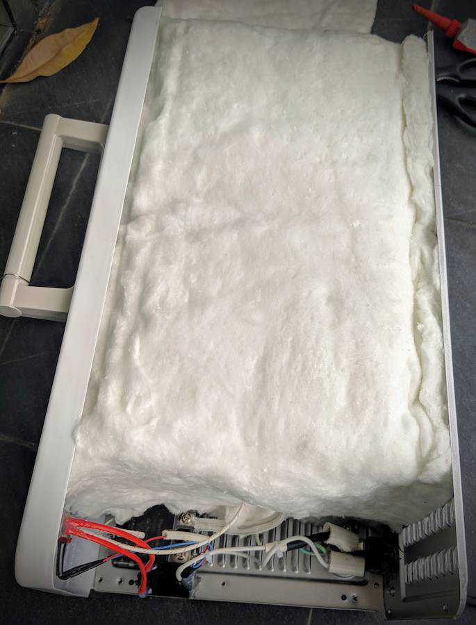
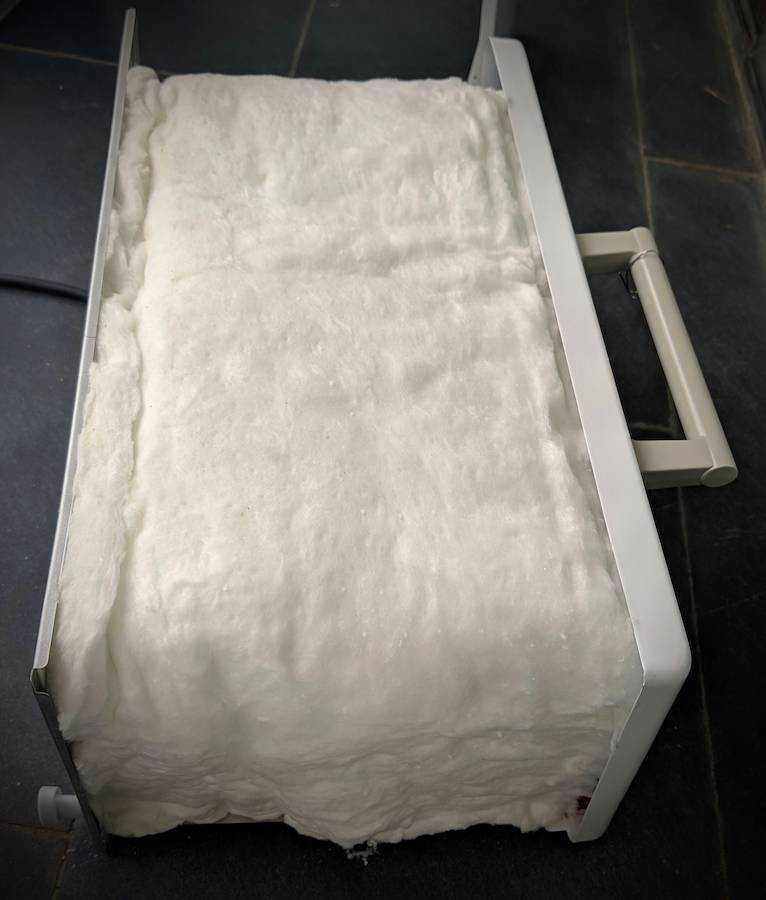
- Insulate the gap between the inner and outer walls on the top and sides with thick ceramic fiber insulation.
- Replace tray with folded foil.
- Partially cover front glass with foil.
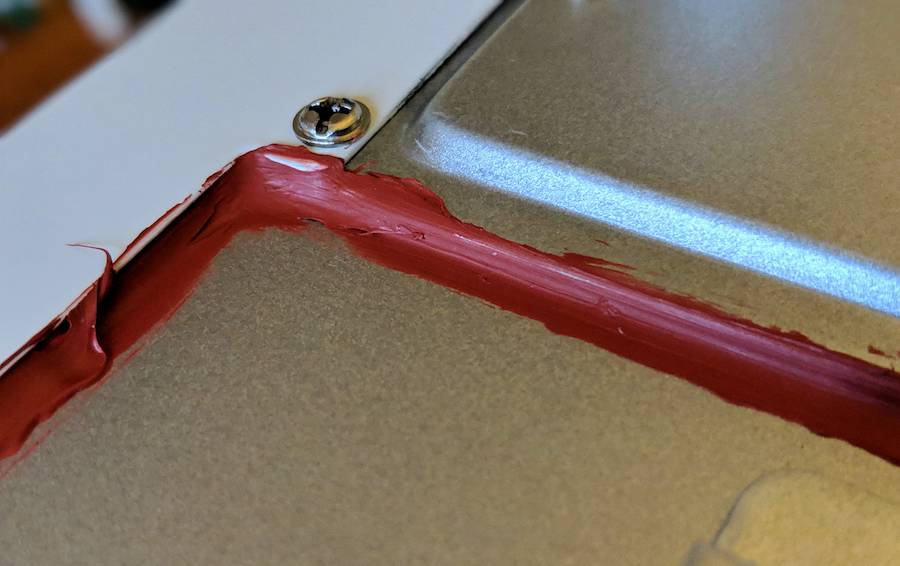
Silicone seals
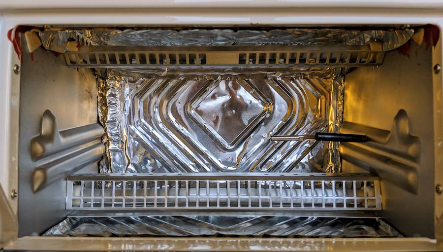
Internal insulation, door foil, and replacement tray
Ramp rate improved 188% with modifications and insulation additions
As a result of these changes, the ramp rate improved from 0.84 to 2.42°C/sec. in the 100->200°C range.
The foil/insulation lining and removal of the tray gave the most benefit, followed by the inner insulation and gap sealing. The outer insulation provided less benefit than expected, but contributed to a better ramp rate at higher temperatures (and a much cooler outer surface/electrical area).
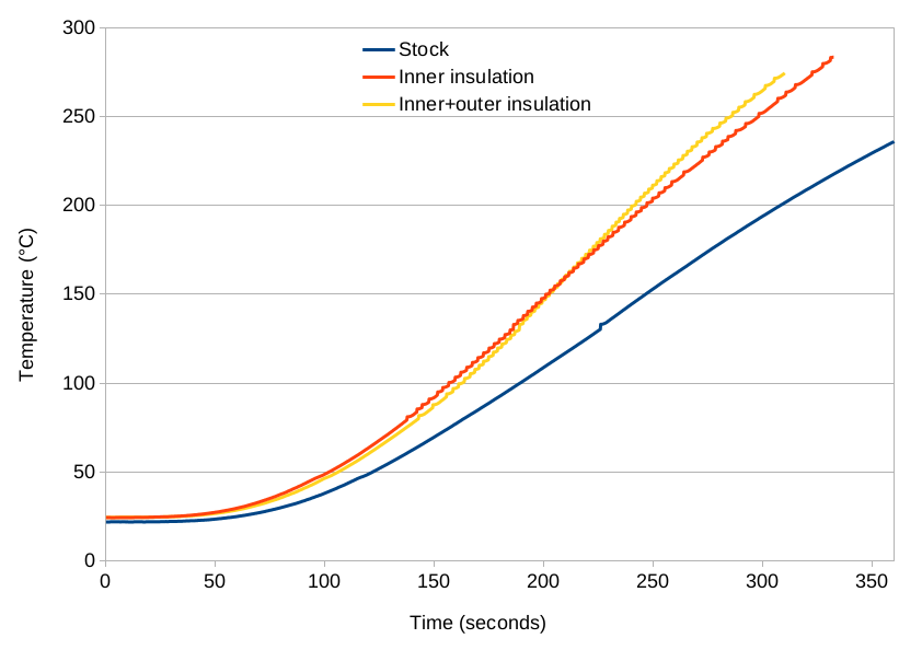
Removal of the stock tray resulted in a much better ramp rate.
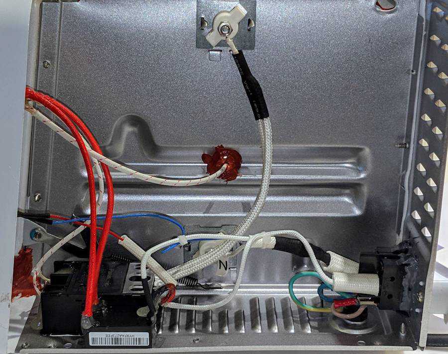
Internal electrical modifications
Controlling the power
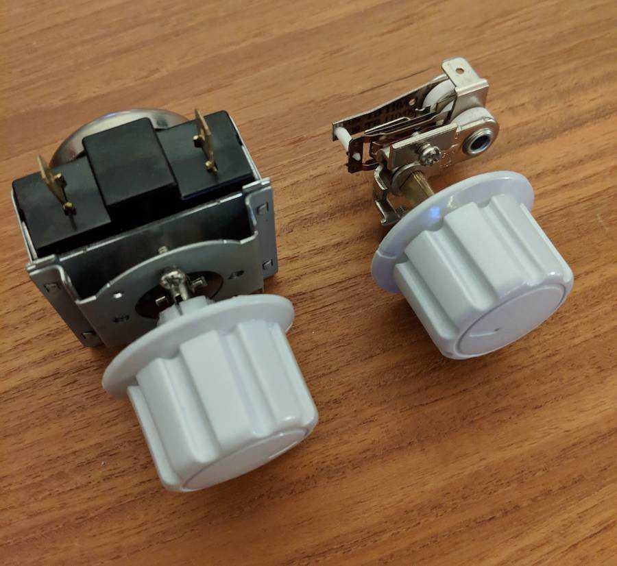
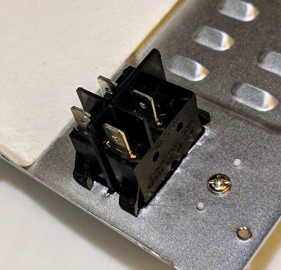
Beyond improving the oven’s ability to raise the cavity temperature, a method of controlling the power level is needed. The original controls used mechanical switches incorporating a thermostat:
At 1200W (~5A), switching power to the oven requires some care. Although the heating elements in the oven are primarily resistive, they present sufficient inductance to cause problems if we try to switch them on and off while a high current is flowing. The breaking (i.e. turning off) of a current in an inductive circuit generates a voltage across the broken contact as the magnetic field collapses (see counter-electromotive force).
This presents two problems:
- Firstly, in a physical switch the instantaneous break and resultant potential across the contacts will result in arcing, which will in turn damage the contacts over time.
- Secondly, the rapid change will generate electromagnetic interference.
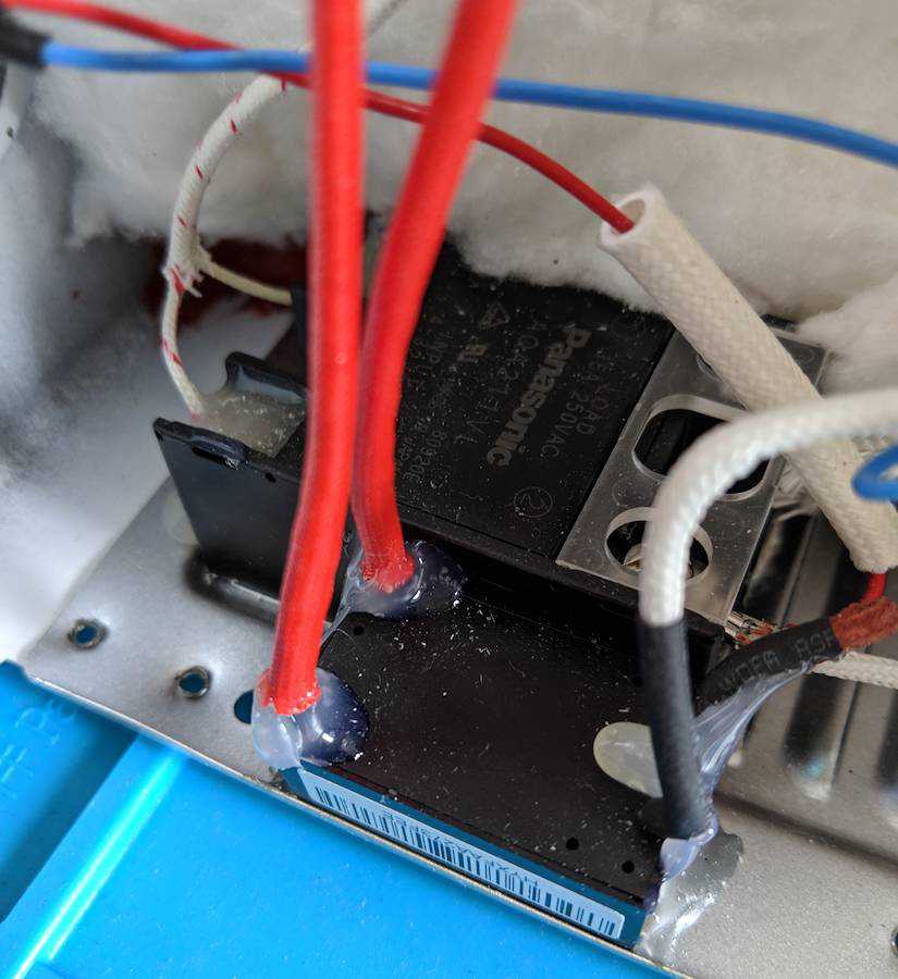
Both of these problems can be easily avoided in an AC circuit by switching the elements when the current is zero. This is accomplished through the use of a zero-crossing solid state relay (SSR). Strictly speaking, the SSR switches when the voltage is zero, but given the limited inductance of the heating elements, there will not be too much of a voltage/current lag.
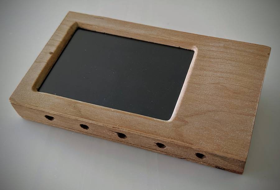
Controller power and I/O
To power the control circuitry and SSR, a small switching supply was installed along with the SSR. For safety and to reduce the exposure of the electronics to high temperatures, all other control circuitry will sit outside the oven:
- SSR relay, thermocouple, and 5V power supply mounted inside the oven
- Controller, interface, and door servo outside the oven
Within the oven, the chassis is earthed, the high and low voltage sections are physically separated, secured in place, and all low voltage sections and contacts doubly insulated.
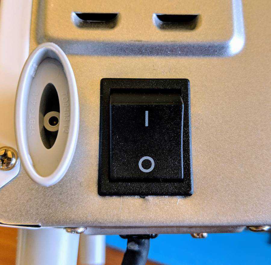
Rather than using a soft power switch on the controller and subjecting the DC power supply to constant power, a physical power switch was added to the rear of the chasis:
On the front panel, a DC socket supplies power and an RCA socket provides access to the SSR DC driving contacts. The thermocouple wire connects directly to the controller to avoid a thermal gradient between the encoder IC (where the cold junction temperature is measured) and the actual cold junction of the thermocouple.
Front panel modifications
With the oven sealed, insulated and modified for external electronic control, it now requires a controller.