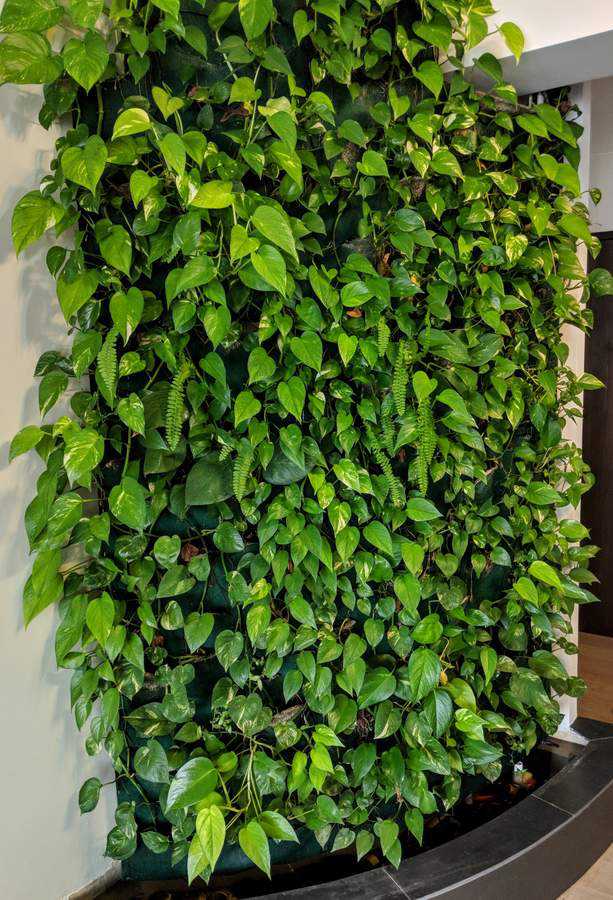
While renovating my apartment, I designed and built a garden wall as a partition between the living and entry areas.
The design is relatively simple. The wall itself is plaster covered solid brick and follows a gentle curve. Mounted on the wall face are several sheets of Sintra board (expanded closed-cell PVC), held about 100mm off the wall with aluminium brackets. Two layers of 5mm polyester felt are stapled to the Sintra board and the plants’ roots sit between the two felt layers (via an incision in the front layer).

The wall construction is relatively simple.
At the base of the wall is a water trough. A submerged pump periodically pumps water from the trough to the top of the wall, where it drains from a horizontally mounted PVC pipe with small holes at fixed intervals. The water flows down the felt, watering the plants along the way, and drains back into the trough.
Plants need food
Plants typically cannot survive by consuming CO2 and H2O alone. Although predominantly carbon, hydrogen, and oxygen, plants also need other mineral elements to survive and grow. Namely, nitrogen, potassium, phosphorus, calcium, magnesium, sulfur, and several others.
While healthy soils provide these elements, the plant wall has no soil. A typical hydroponic approach is to add the required nutrients to the water as required. In an effort to reduce required maintenance, I went for a natural alternative and populated the water trough with fish. Fish manure is chemically similar to other animal manures and is an effective fertilizer:
The manure samples from the commercial farms averaged 2.83% nitrogen (N), 2.54% phosphorus (P), 0.10% potassium (K), 6.99% calcium (Ca), and 0.53% magnesium (Mg) on a dry-weight basis. The Chemical Composition of Settleable Solid Fish Waste (Manure) from Commercial Rainbow Trout Farms in Ontario, Canada
In effect what I tried to create was a closed (ignoring sunlight) ecosystem, where sunlight fuels the growth of algae and the plants, the fish consume the algae and dead, dropped plant material, and fertilize further growth with their manure.
This is perhaps a tad optimistic in that it assumes that the biomass of the wall remains constant and that all the dead leaves etc. from the wall fall back into the water and are recycled, but was worth a try. The fish were also introduced to ensure that no mosquitos breed in the water, and so serve a useful function regardless.
I started with only four fish, but romance was in the water it seems, as within two years, I had around thirty, seemingly healthy fish spending their days lazily fertilizing the wall.
A grisly demise
Since the water is pumped up and drains down the wall once or twice a day, evaporation is somewhat rapid. It’s typically necessary to add some water every week. This is fine when I’m at home, but I travel regularly and at times may be away for months at a time. During such times, a house minder takes care of things.
Unfortunately while offsite building a pool, some miscommunication with the house minder resulted in the water almost entirely evaporating and some of the larger fish suffering a grisly demise.
Intent on ensuring the replacement fish would never suffer such a fate, I decided to automate the water replacement process.
Automating the water replacement
When I built the wall I envisaged requiring regular top ups and so installed a water line with a simple manual valve directly into the trough. Automating the process simply involves sensing the water level, deciding what to do based on that sensor data, and turning the water on/off as required. In other words, a water level sensor, some control electronics, and a solenoid.
Sensing the water level
There are a variety of methods available to determine fluid levels. Ultrasound can be used under or above the water to detect the bounce from the surface, laser time-of-flight is possible for opaque liquids, pressure sensors can determine the depth, capacitance sensors will work without even contacting the liquid. In the absence of needing detailed information about the precise water level, I’m going low tech and using a simple float sensor to detect a water full condition.

Float sensor in place
To turn the water on and off, a 12V solenoid is connected directly after the manual valve. This is the same sort of thing used in washing machines and dishwashers.
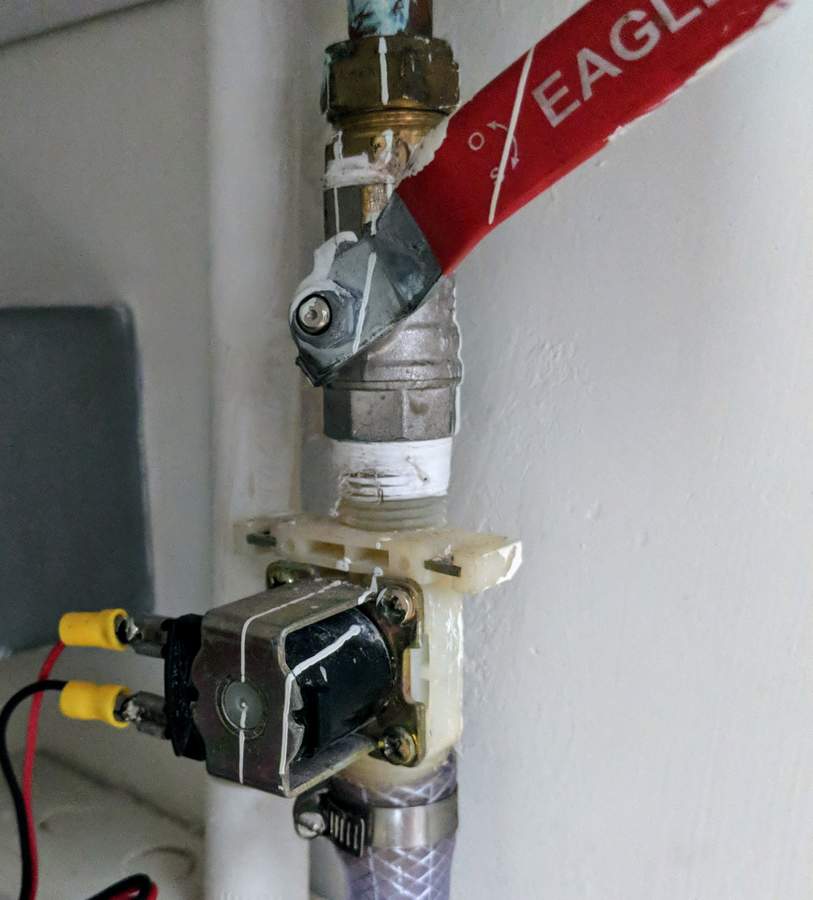
12V solenoid controls the water supply
Software is eating the world
If I had undertaken this project last decade, I would likely have built the control electronics out of discrete ICs, probably a 555 timer, counter, and passive support components. But in today’s world of cheap integrated microcontrollers, where a 20 MHz, 8-bit AVR RISC microcontroller can be had for less than a (US) dollar, implementing the design in software becomes a lot more attractive.
To this end, I’m using the ATTiny85, an 8-bit, 20MHz, AVR RISC-based microcontroller with the following specs:
- 512-Byte EEPROM, 512-Byte SRAM
- 6 general purpose I/O lines
- 32 general purpose working registers
- One 8-bit timer/counter with compare modes and one 8-bit high speed timer/counter
- Internal and external Interrupts,
- 4-channel 10-bit ADC
- Programmable watchdog timer with internal oscillator
- 3 software selectable power saving modes
Of course all of those peripherals aren’t available to a single application because it only has 8 pins:
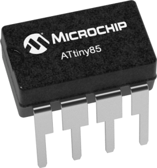
ATTiny85 8-bit microcontroller
Image courtesy of Microchip Technology Inc.
The solenoid is a 12V type drawing around 1A when on and so I’m using a 12V power supply. Since the ATTiny85 runs on 2.7 V ~ 5.5 V, a voltage regular of some sort is required.
A simple 3-pin 7805 regulator is sufficient. Although a linear regulator (effectively using a resistor to drop the voltage and dissipate the excess energy as heat) such as the 78xx series is a lot less efficient than using a separate switching supply, in this application the ATTiny and driving MOSFET use extremely small amounts of power and the power lost will be a small fraction of a Watt.
The solenoid itself is driven from the ATTiny output by way of a NTD4815N power MOSFET. A switch is also included to manually activate the solenoid when manual filling is desired.
I’ve also included two status LEDs to provide feedback on what is going on inside the controller logic. The full circuit is as follows:
The controller schematic is quite simple as all the logic is in the microcontroller program.
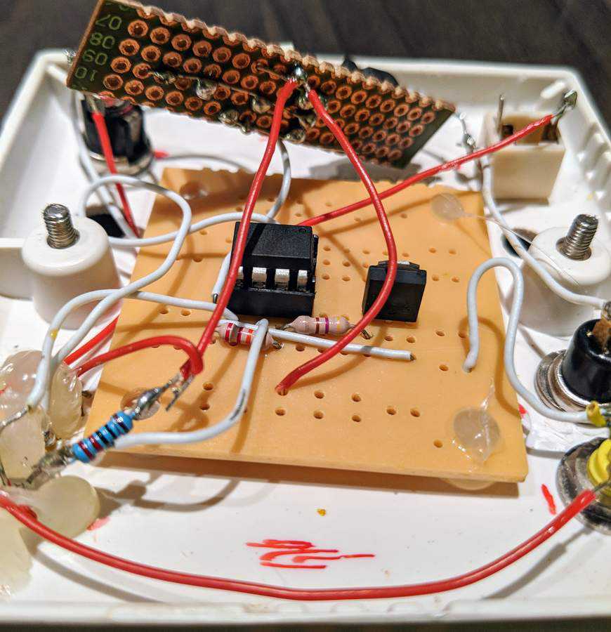
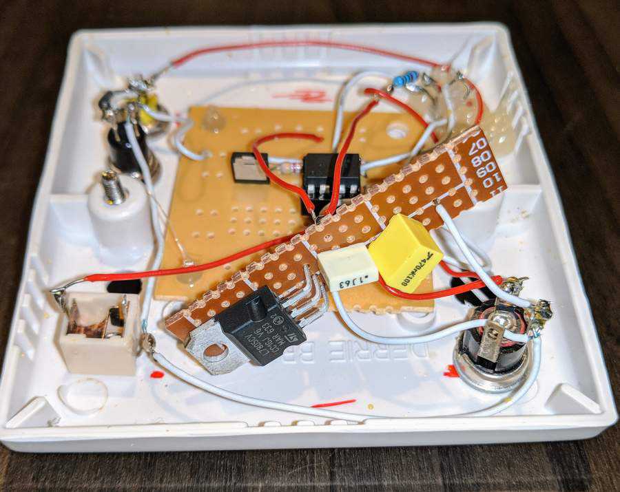
Given the simplicity of the circuit, I used a generic breadboard PCB rather than a custom piece. It’s ugly as hell, but gets the job done.
Mounting
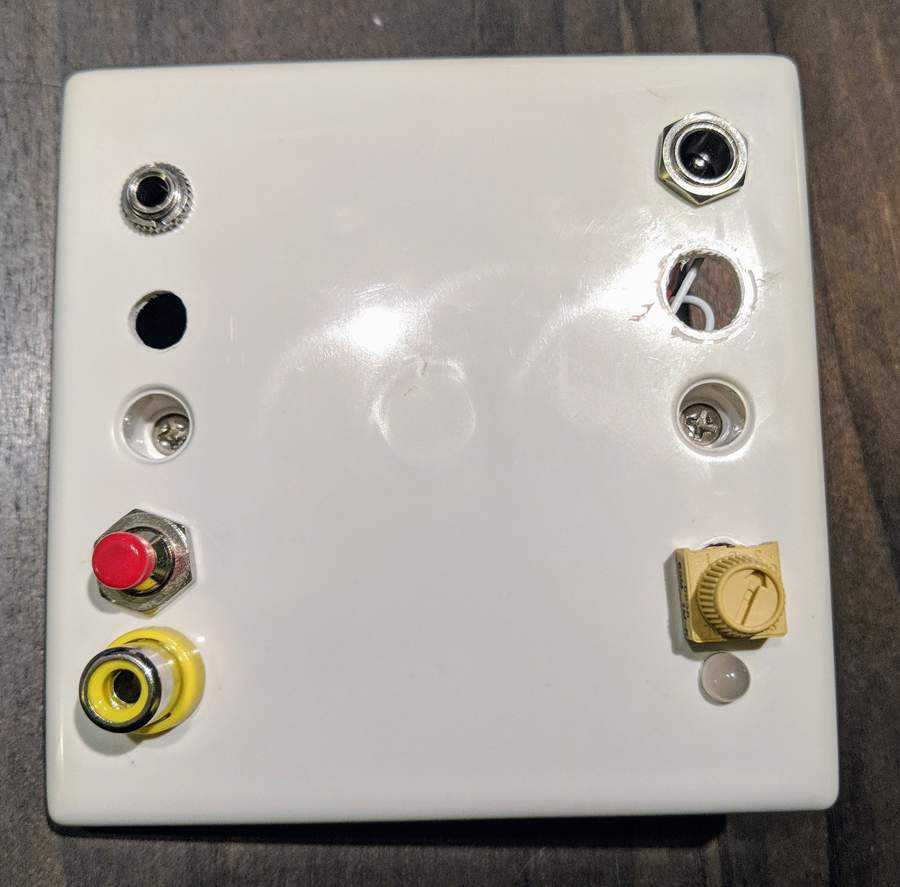
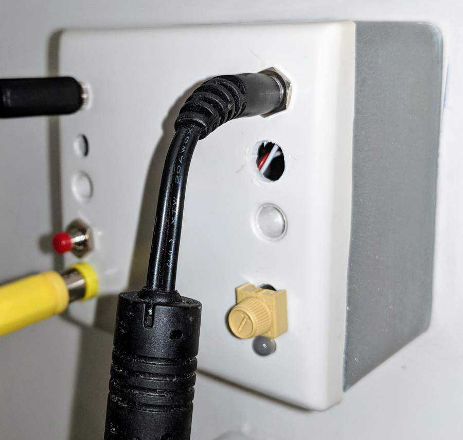
The board is mounted on the back of a standard electrical faceplate, which is then mounted on the wall behind the garden wall.
Software
The controller program is very straighforward. It simply needs to check the water level at set intervals and if low, add water.
The only complication is that the water from the trough is periodically pumped to the top of the wall, where it slowly drains back down to the trough, watering the plants as it goes. During this time the water level will appear low, but it is temporary. Therefore if we detect the water level as low, we need to wait a while and then check if it is still low. The time we wait must be greater than the time that the watering pump is on, but less than the time between watering events.
The basic program is thus as follows:
loop forever
    If water level is low
        delay for x mins
        If water level is still low
            turn on water for y secs
    delay for z mins
end loop
The water trough has an overflow drain to ensure my living room isn’t turned into a lake should things go haywire. With the remote possibility of this drain becoming blocked and the float sensor failing in a low state, the controller program will enter an error state if the sensor continues to measure low after a set number of consecutive fills.
Programming
I’m not going to go into detail about how to program the ATTiny. There are many online resources explaining this better than I could. In addition to these, I would strongly recommend referencing the official datasheet if you are doing any ATTiny development as it is the definitive reference and is surprisingly readable.
The full code is included below for reference.
The compiled binary totals 506 bytes (692 using -O2 optimizations) and uses 1 byte of SRAM (to keep track of consecutive fills) excluding stack space.
Full source code listing
// The MIT License (MIT)
//
// Copyright (c) 2017 duk.io
//
// Permission is hereby granted, free of charge, to any person obtaining a copy
// of this software and associated documentation files (the "Software"), to
// deal in the Software without restriction, including without limitation the
// rights to use, copy, modify, merge, publish, distribute, sublicense, and/or
// sell copies of the Software, and to permit persons to whom the Software is
// furnished to do so, subject to the following conditions:
//
// The above copyright notice and this permission notice shall be included in
// all copies or substantial portions of the Software.
//
// THE SOFTWARE IS PROVIDED "AS IS", WITHOUT WARRANTY OF ANY KIND, EXPRESS OR
// IMPLIED, INCLUDING BUT NOT LIMITED TO THE WARRANTIES OF MERCHANTABILITY,
// FITNESS FOR A PARTICULAR PURPOSE AND NONINFRINGEMENT. IN NO EVENT SHALL THE
// AUTHORS OR COPYRIGHT HOLDERS BE LIABLE FOR ANY CLAIM, DAMAGES OR OTHER
// LIABILITY, WHETHER IN AN ACTION OF CONTRACT, TORT OR OTHERWISE, ARISING
// FROM, OUT OF OR IN CONNECTION WITH THE SOFTWARE OR THE USE OR OTHER DEALINGS
// IN THE SOFTWARE.
//
// ----------------------------------------------------------------------------
//
// 12-Aug-2017
//
// Control firmware for automatic water level maintainer.
//
// Checks water level periodically. If low, will wait and check again to
// ensure level is not low due to periodic waterfall pumping. If still low,
// water valve is opened for a short period to add water. The valve open
// duration is set via a potentiometer.
//
// If water level is consistently measured low too many times, alarm is
// triggered and execution halts.
//
// Target
// ------
// ATTiny85
//
// GPIO
// ----
// All GPIO is setup on port B
// - OUT BUZZER_PIN      : Buzzer output. High = buzzzzz
// - OUT SOLENOID_PIN    : Water control solenoid. High = water flowing
// - OUT LED_GREEN_PIN   : Green status LED. Low = on
// - OUT LED_PIN_RED     : Red status LED. Low = on
// - IN  SENSOR_PIN      : Water level sensor is connected between this pin and
//                       : ground. Open circuit on water level low, short to
//                       : ground on water level okay.
//                       : pullup)
// - IN  POT_ADC_CHANNEL : Water fill duration input.
//                       : Duration = Vpin/Vcc * max_water_on_time_s

#include<stdbool.h>
#include<stdint.h>
#include<avr/io.h>
#include<avr/delay.h>

static void setupIo(void);
static void checkAndFill(void);
static bool isLevelLow(void);
static uint16_t getFillTime(void);
static void fill(void);
static uint8_t readAdc(uint8_t channel);
static void haltOnError(void);
static void ledFlashFast(uint8_t port, uint8_t n);
static void ledFlashSlow(uint8_t port, uint8_t n);
static void beep(uint8_t secs);
static void delayS(uint16_t secs);
/// Must be pin on port B
static void ledOn(uint8_t port);
/// Must be pin on port B
static void ledOff(uint8_t port);

// ** Note: All input/outputs must be PORTB **

#define BUZZER_PIN PB5
#define SENSOR_PIN PB4
#define SOLENOID_PIN PB2
#define LED_GREEN_PIN PB1
#define LED_PIN_RED PB0
#define POT_ADC_CHANNEL 3

// **

static const uint16_t check_interval_s = 30 * 60;
static const uint16_t dbl_confirm_interval_s = 90 * 60;
static const uint16_t max_water_on_time_s = 90;
static const uint8_t max_consec_files = 5;

int main(void)
{
    setupIo();
    while(1) {
        checkAndFill();
        delayS(check_interval_s);
    }
    return 0;
}

static void setupIo(void)
{
    // Setup inputs and outputs
    DDRB |= (1<<SOLENOID_PIN) | (1<<LED_GREEN_PIN) | (1<<LED_PIN_RED) | (1<<BUZZER_PIN);
    DDRB &= ~(1<<SENSOR_PIN);
    ledOff(LED_PIN_RED);
    ledOff(LED_GREEN_PIN);

    // Setup ADC
    ADMUX =
            // Vcc ref.
            (0<<REFS1) | (0<<REFS0) |
            // left shift result
            (1 << ADLAR);
    ADCSRA |=
            // 125 kHz sample rate (oscillator=8MHz, clock=1MHz, prescaler=8)
            (1<<ADPS1) | (1<<ADPS0) |
            // enable
            (1<<ADEN);
}

static void checkAndFill(void)
{
    static uint8_t consecutive_fills = 0;

    ledFlashSlow(LED_GREEN_PIN, 1);

    // If level is low, wait and check again in
    // case this is just the waterfall running.
    if (isLevelLow()) {
        ledFlashFast(LED_GREEN_PIN, 1);
        delayS(dbl_confirm_interval_s);
        ledFlashSlow(LED_GREEN_PIN, 2);
        if (isLevelLow()) {
            if (consecutive_fills >= max_consec_files) {
                haltOnError();
            }
            fill();
            consecutive_fills++;
        }
        else {
            consecutive_fills = 0;
            ledFlashFast(LED_GREEN_PIN, 3);
        }
    }
    else {
        consecutive_fills = 0;
        ledFlashFast(LED_GREEN_PIN, 3);
    }
}

static bool isLevelLow(void)
{
    // Enable pull up only for measurement to reduce sensor wear
    PORTB |= (1<<SENSOR_PIN);
    _delay_ms(1);
    // Float switch is open circuit if water is
    // low, short to ground if water is high.
    bool sensorVal = PINB & (1<<SENSOR_PIN);
    PORTB &= ~(1<<SENSOR_PIN);
    return sensorVal;
}

static uint16_t getFillTime(void)
{
    uint8_t potLevel = readAdc(POT_ADC_CHANNEL);
    return max_water_on_time_s * potLevel / 255;
}

static void fill(void)
{
    PORTB |= (1<<SOLENOID_PIN);
    ledOn(LED_GREEN_PIN);
    delayS(getFillTime());
    PORTB &= ~(1<<SOLENOID_PIN);
    ledOff(LED_GREEN_PIN);
}

// 8-bit read, valid channel = 0 -> 3
static uint8_t readAdc(uint8_t channel)
{
    ADMUX &= 0xf0;
    ADMUX |= channel;

    // Start conversion and wait for result
    ADCSRA |= (1<<ADSC);
    while ( (ADCSRA & (1<<ADSC)) );
    return ADCH;
}

static void haltOnError(void)
{
    ledOn(LED_PIN_RED);
    while(1) {
        delayS(60 * 60);
        beep(1);
    }
}

static void beep(uint8_t secs)
{
    for (int i = 0; i < (secs * 250); i++) {
        PORTB |= (1<<BUZZER_PIN);
        _delay_ms(2);
        PORTB &= ~(1<<BUZZER_PIN);
        _delay_ms(2);
    }
}

static void ledFlashFast(uint8_t pin, uint8_t n)
{
    for (int i = 0; i < n; i++) {
        ledOn(pin);
        _delay_ms(300);
        ledOff(pin);
        _delay_ms(300);
    }
}

static void ledFlashSlow(uint8_t pin, uint8_t n)
{
    for (int i = 0; i < n; i++) {
        ledOn(pin);
        _delay_ms(1000);
        ledOff(pin);
        _delay_ms(1000);
    }
}

static void delayS(uint16_t secs)
{
    for (int i = 0; i < secs; i++) {
        _delay_ms(1000);
    }
}

static void ledOn(uint8_t pin)
{
    PORTB &= ~(1<<pin);
}

static void ledOff(uint8_t pin)
{
    PORTB |= (1<<pin);
}

