534 meters of bar plus mesh to be precise.
As discussed during the detailed design, the retaining walls and wall footings contain a lot of steel. Specifically, N12 and N16 bars. This type of steel reinforcement inside concrete is typically referred to as rebar, or reo, depending on which part of the world you’re in, and adds tensile strength to the concrete.
The bars themselves are standardized. The N classifier tells us that they are Normal strength, which is a yield strength of 500 MPa and a tensile strength in excess of that.
Yield strength is the strength beyond which, the steel will deform plastically. Think of your average steel coat hanger. If you flex it gently, the bend is elastic and it will return to it’s original shape when you release it. But if you flex it too hard, it will bend and the bend will remain when you release the pressure. This is the yield point. Our bars are have a yield strength of 500 mega pascals, which is roughly the pressure a 50 million kilogram weight exerts when sitting on a one square meter area.
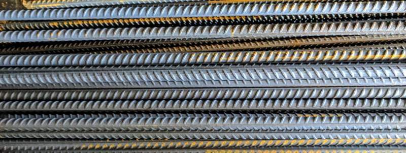
The number is the diameter of the bar. So N16 is 16mm diameter Normal strength bar. They are also deformed, with ribs along their surface (see image below) rather than being smooth. This allows the bars to better bond with the concrete.

N12 deformed bar
As well as reinforcing the wall and footing separately, the bars connect the two together and as such have a number of bends. The stepped footings also require the steel to be bent to follow the footing steps. Although bars can be ordered cut and bent as required, for fun and to save money we’ll be doing our own cutting and bending and buying stock 6 meter bars.
The high level tasks to get the steel work ready for concrete are as follows:
Step 1 - Cut it
There are specialist pneumatic tools for cutting rebar, but these aren’t really an option for a DIY project. A chop saw is a good option, but is troublesome for long pieces; also I don’t own one. My cutting tool of choice therefore is an angle grinder with cutting blade.
Safety first
Angle grinders are among the most dangerous power tools you’ll find in the average home. Mine is an AEG with 125mm diameter blade and a maximum RPM (revolutions per minute) of 11,000. Let’s take a look at the physics:
Max. revolutions per minute = 11000
Blade radius = 62.5mm

Max. revolutions per second
= 11000 / 60
= 183.3

Blade circumference
= 2 * Pi * radius
= 2 * Pi * 62.5
= 392.7mm
= 0.3927m

Blade speed at the edge:
= 0.3927 * 183.3
= 72.0 meters per second
= 259.2 kilometers per hour (161.1 miles per hour)
The damage that can be cause by a piece of formerly intact cutting disc coming tangentially out of the angle grinder at ~260 km/hr is frightening.
The high speed disc of angle grinders does not respect anatomical boundaries or structuresDr Lachlan Carter, Maxillofacial Surgeon
I would advise never using an angle grinder without a face guard, impact resistant gloves, and of course the grinder guard itself. Keep yourself perpendicular to the wheel and keep the guard between the blade and your body.
Minimizing waste
With the cutting tool sorted, my mind quickly moved to the problem of optimal cutting methods to minimize wastage. Rebar comes in a number of standard lengths, but 6 meters is typical and is the length that I’m using.
The problem of cutting standard lengths to maximize yield is known as the Cutting stock problem, which is effectively the Knapsack problem and whose solution is unfortunately NP hard.
For example, assuming we have a number of 6000mm bars and require the lengths of bar shown below, what is the optimal way to cut them?
| Length (mm) | Number required |
|---|---|
| 3320 | 4 |
| 3100 | 4 |
| 1300 | 4 |
| 1100 | 2 |
| 2700 | 3 |
| 2500 | 3 |
| 2470 | 3 |
I looked for online solvers and found the following two:
Unsurprisingly, both produced identical results. With over one hundred pieces to cut, I set to work.

Step 2 - Bend it
There are two types of retaining walls in this project. The rear wall where the footing extends uphill, and the walls surrounding the pool where the footing extends away from the pool. The required reinforcement differs for these two wall types.
Reinforcement details for the two retaining wall types
As can be seen above, both wall types require significant amounts of bent bars. In addition the longitudinal N16 bars in the footing must be bent when the footings step down (i.e. go down the slope like stairs). The bars must be bent to follow the footing in a zigzag fashion.
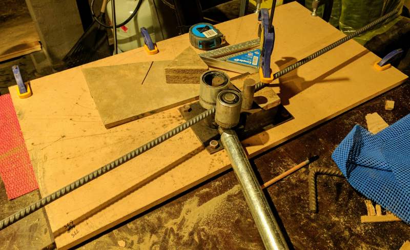
To bend steel on a budget, I bought a manual rebar bending tool on Aliexpress for US$50, a piece of wood to mount it on, and a two meter steel tube for leverage as a handle.
Radius matters
A bend is a bend is a bend right? Not exactly. The purpose of rebar is to provide tensile strength for the concrete. If the bar is bent too sharply, the strength of the steel may be compromised. Standards differ between regions, but the minimum bend diameter for N12 and N16 bar here is typically 4-5x the diameter of the bar (depending on what the bent bar is being used for). Bends tighter than this risk damaging the bar and impairing it’s tensile strength.
The problem I encountered was that the pins on my rebar bender have a diameter that is only around 25mm, or ~2x the N12 bar diameter. My solution was to cut several pieces of steel tube with increasing diameters like a set of matryoshka dolls and slot these over the bending pin.
Once the pieces were in place, I clamped the wood backing to the table and proceeded to bend.

Ready to bend!
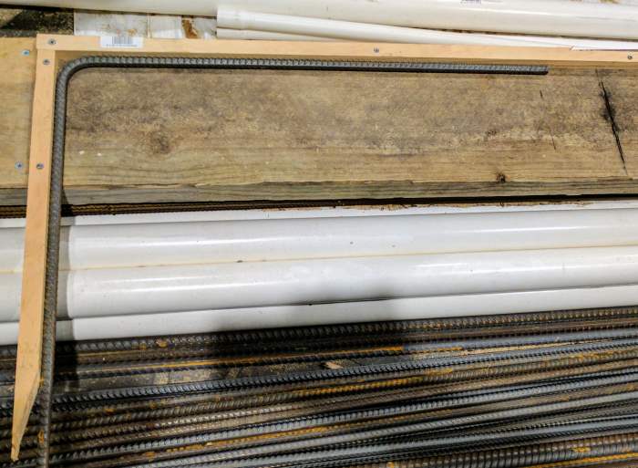
The next issue I encountered was when to stop. Most of the bends call for a right angle. For bars where the bent part is short, the exact angle doesn’t need to be too precise, but a lot of the starter bars are 850 x 870mm and so an imprecise bend will result in a bar that isn’t vertical. So I quickly built a right angle testing bed, and that combined with a square edge allowed for pretty precise bends.

Right angle test bed
With the right tools in hand, I began bending all the footing and starter bars for the rear retaining wall. These were the simplest as the bent part is relatively short and there is only a single bend.
Bars for the flower bed walls were far more challenging. Instead of using two bars, a single “U” bar with two right angle bends is used to connect the walls. Creating the two bends was relatively simple, but ensuring that they were on the same plane was anything but.
Bar bender repairs
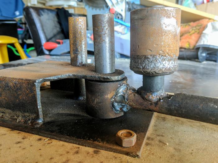
During the course of creating the bars, it became evident that the bar bender wasn’t going to hold up for all of the bends. The increased radius put much higher pressure on the roller than it was designed for, which first bent and then outright snapped off at the base. This was easily rectified with US$15 and a quick trip to the local metal shop, allowing me to complete of the required bends quicker than I had originally planned.

Repaired bender (roller re-welded)
Now I just need to work out how to fit it all together.


