
This part five of a six-part post:
- System design and planning
- Circuit and PCB design
- Mechanical design
- Firmware
- Installation and external power
- Conclusion, problems and screwups
Installation
Sometimes the hard work is already done for you
In one of the more surreal moments of this project, after marking out the 80x80mm square on the wall where the device would sit, I proceeded to drill out a cavity for the back box with my Bosch SDS drill (walls in these parts are cinder blocks/concrete with a thin plaster layer). The bit immediately broke through the plaster, revealing an existing electrical back box filled with newspaper, in almost the precise location I had marked (~3mm off horizontally).
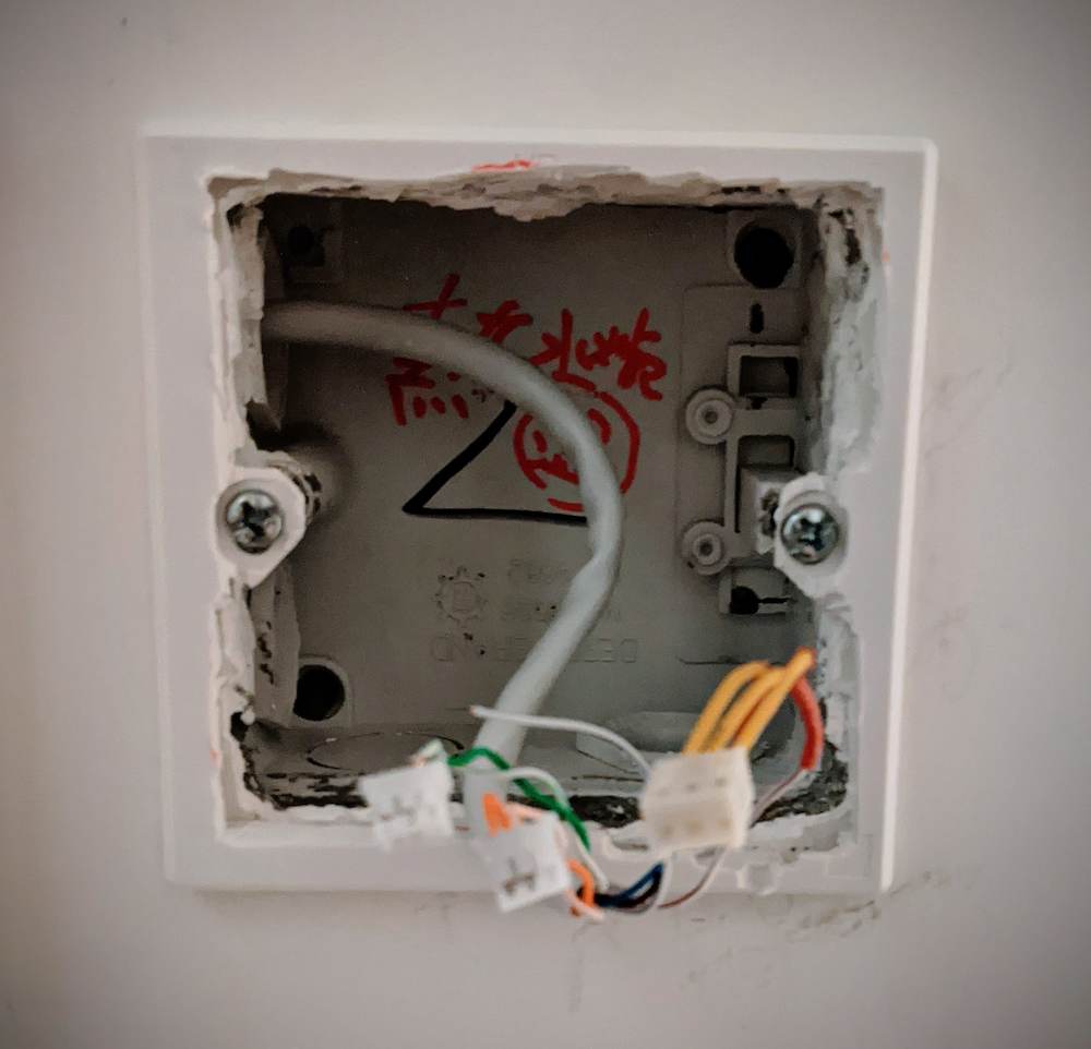
The existing backbox with the cutout electrical socket plate mounted and cable to the power supply/amp inserted.
Connecting the player to the amplifier and power supply
To connect the device to the power supply, amplifier, and amplifier switch, I used some CAT5e cable I had lying around.
The twisted pairs of an Ethernet cable are perfect for the differential audio outputs of the RN52. Differential audio signals run an inverted signal on each conductor, so it is largely immune to interference so long as the pair is kept tightly wrapped (i.e. equally affected by RF noise).
Cat5e uses 24AWG wires. The average current draw of the final device is ~45mA, with peaks from the proximity sensor satisfied by some large. low ESR caps. Even at 100mA, the voltage drop over the 5m length of cable is <0.1V, which is acceptable.
Cat5e has 4 twisted pairs and the player requires 7 conductors:
- left channel +ve
- left channel -ve
- right channel +ve
- right channel -ve
- ground
- 3.3VDC
- amplifier switch sink
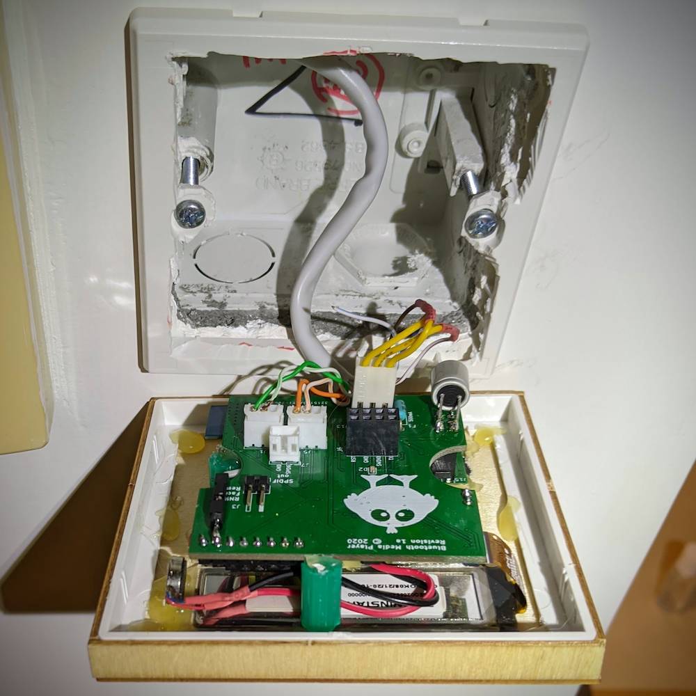
The player has left/right audio, and power connections, and snaps in place onto the power socket frame.
Installing the speaker
I had originally planned to use a somewhat expensive ceiling speaker, but it was out of stock when I needed it, and so I switched to a cheap 8" unit that was available on Amazon.
I wasn’t expecting too much from it, but testing revealed it to be more than capabable of satisfying my modest bathroom listening requirements.
I built a wooden enclosure for it to improve the sound quality and reduce the volume for the upstairs neighbours, although I’m not sure how effective the noise reduction will be given that the enclosure itself is mounted on the ceiling.
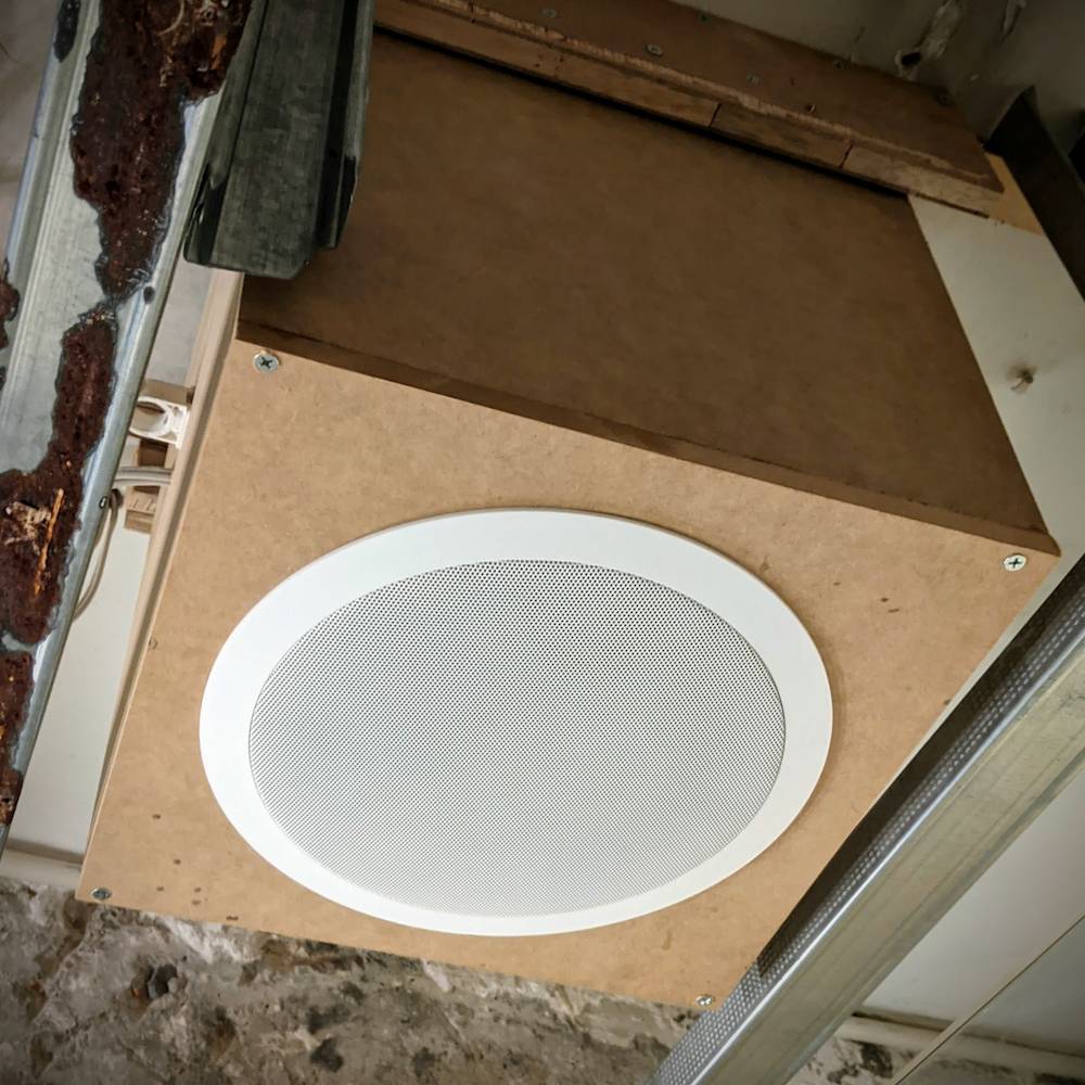
The speaker and enclosure mounted on the ceiling, prior to installing the false ceiling.
Once the drywall ceiling is installed (it was recently removed to repair water damage), the speaker faceplate will sit flush against the ceiling.
Differential audio output -> single ended amplifier input
The RN52 features differential audio output, while the amplifier only has single-ended inputs.
To maintain the noise immunity benefits of the differential audio over the cable length, I did the conversion on the back of the wall plate in the cupboard where the amplifier is housed. Analog electronics is not my forte, but I wired it per the below schematic using a US$2 audio transformer and all seems well.
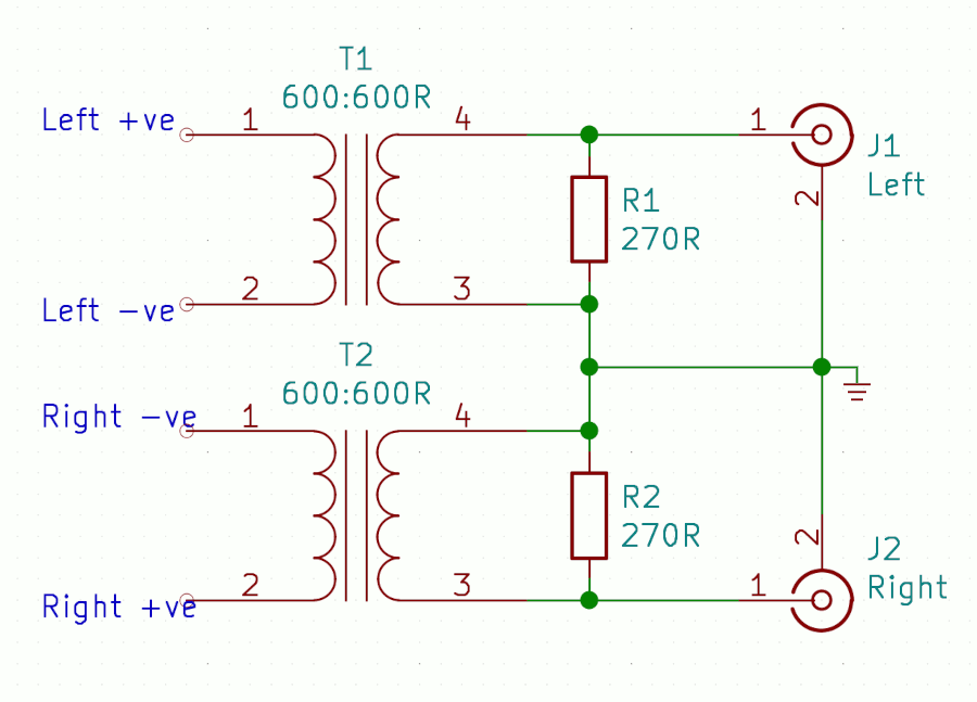
The differential audio is converted to single ended at the amplifier.
The transformer is located on the back of the faceplace that houses the speaker connections (see below).
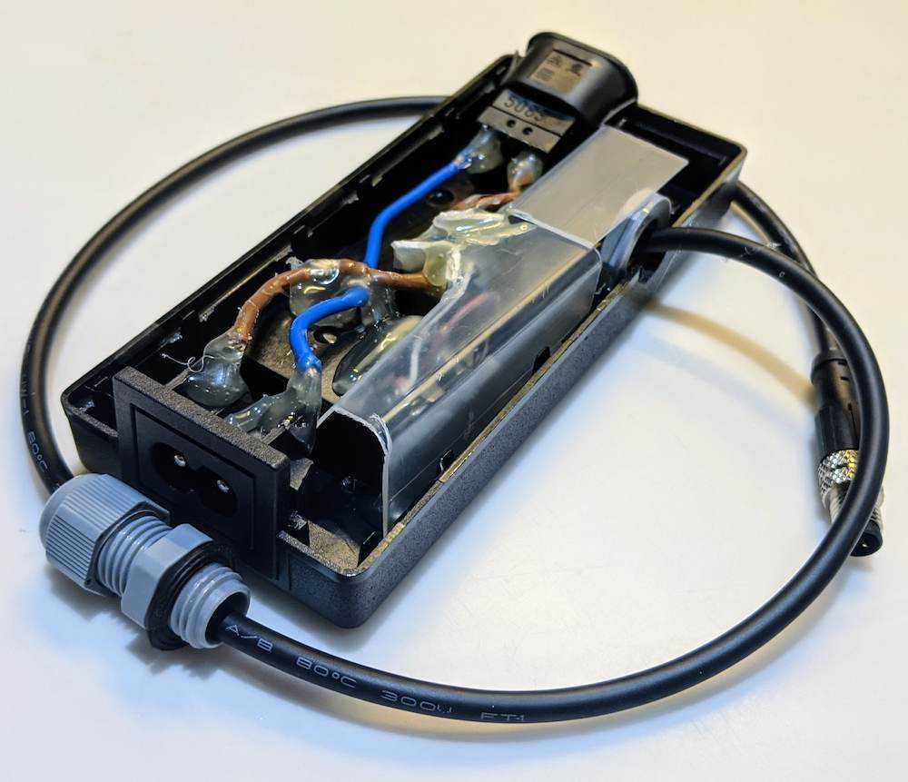
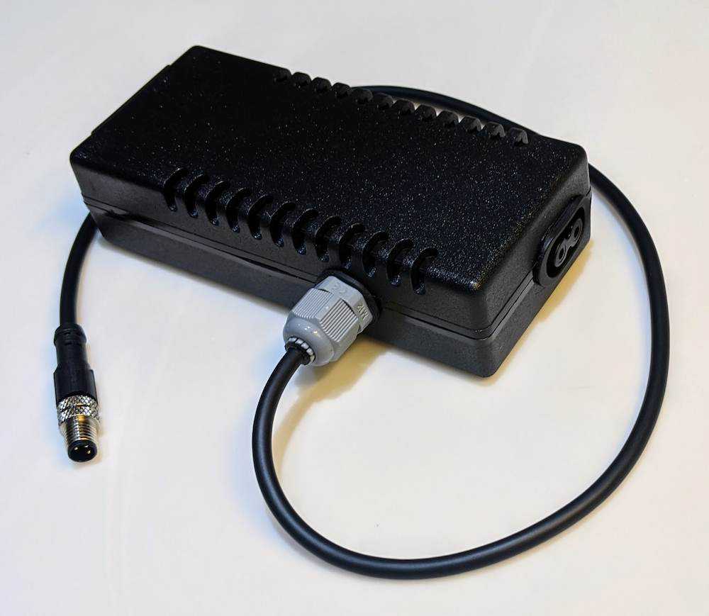
Enclosure for the power supply and amplifer switch
I used a laptop power enclosure to house the 3.3VDC power supply and amplifier power switching relay. The enclosure accepts an IEC C7 (aka figure-8) power cable at one end, and has a female power output at the other. A 3-core cable with M8 connector exits the side, containing the 3.3VDC, ground, and relay sink.
The high and low voltage sections are each fully insulated, physically separated, glued into position, and have an insulating barrier between them.
Connecting it all together
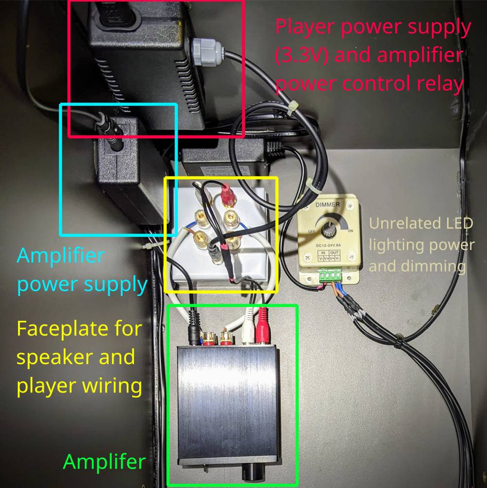
The amplifier and supporting hardware are housed in the top of a nearby cupboard.
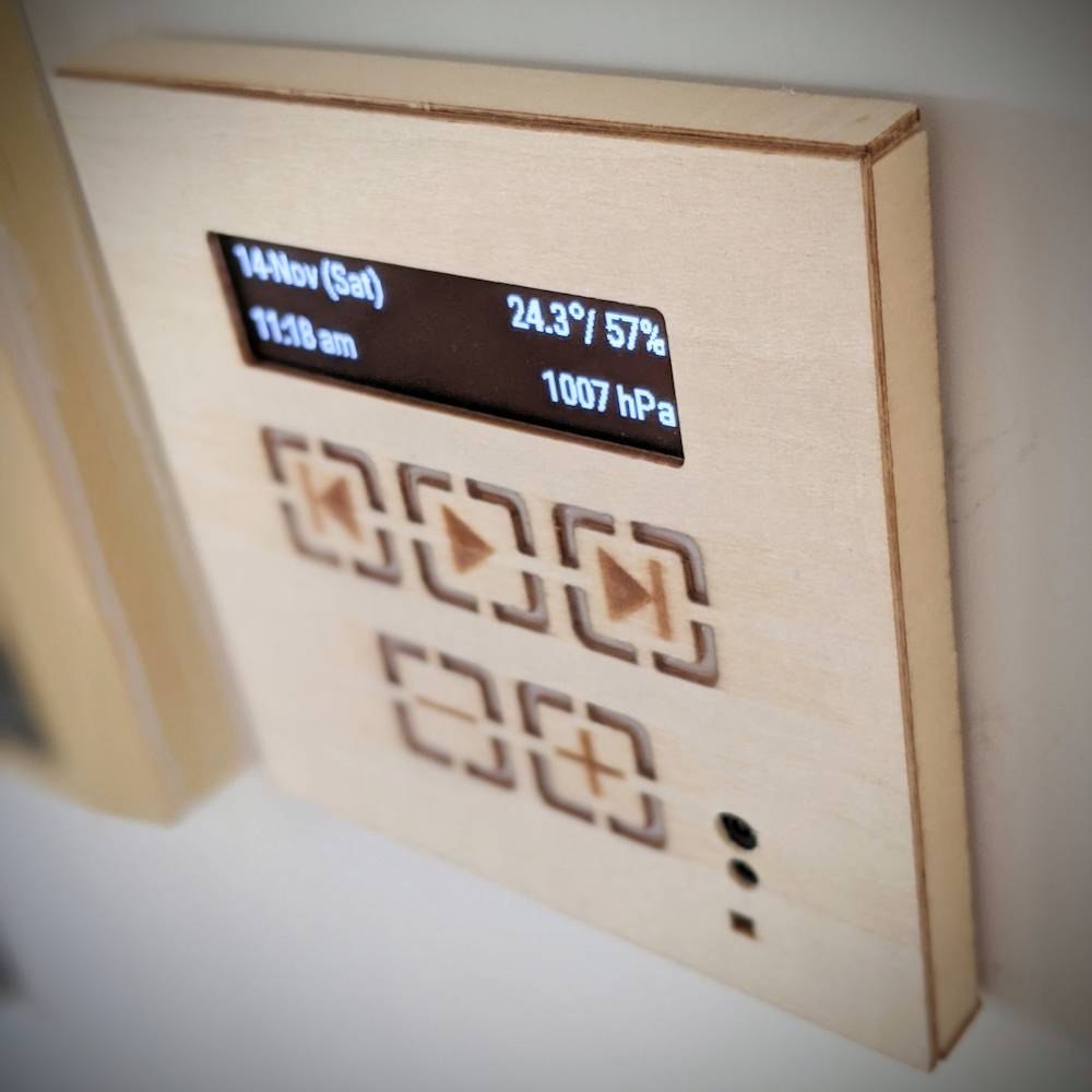
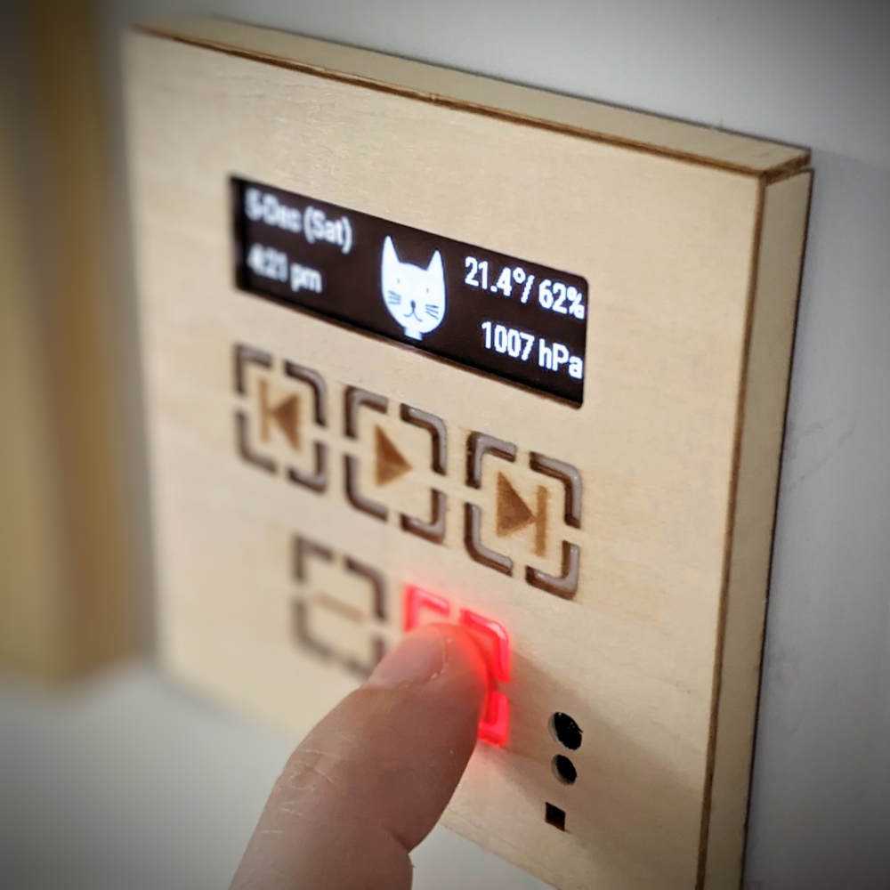
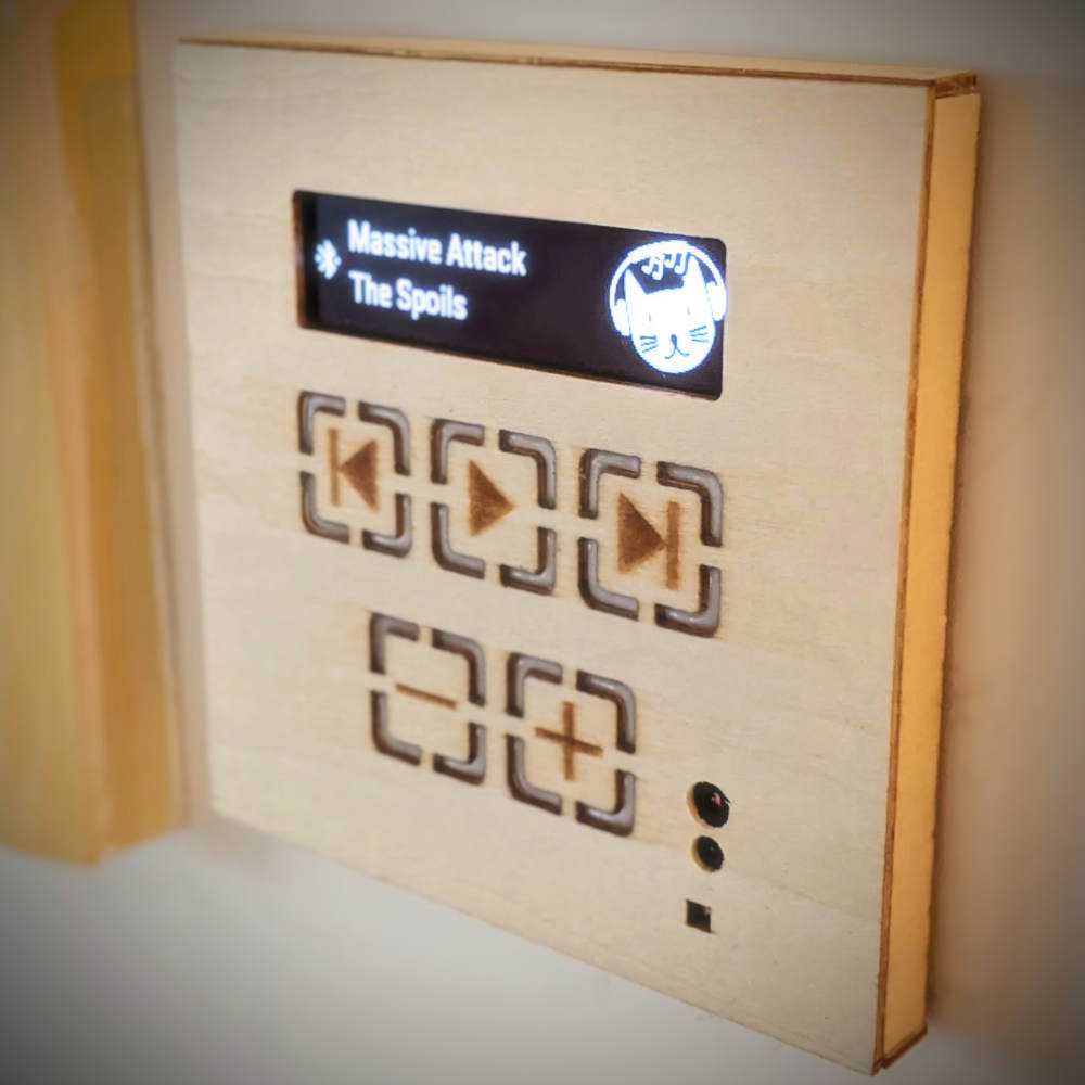
The completed player mounted on the wall