This is the first part of a six-part post:
- System design and planning
- Circuit and PCB design
- Mechanical design
- Firmware
- Installation and external power
- Conclusion, problems and screwups
My latest project is a cat-themed Bluetooth audio player to be permanently installed in my bathroom.
The unit will be housed in a standard electrical junction box on the bathroom wall. This provides for retro-fitting, as well as allowing use of off the shelf components for the in-wall portion. It will include a small screen for display of track metadata.
A separate amplifier housed in a cupboard will connect to a ceiling mounted speaker. To ensure minimal power usage, the amplifier’s power will be switched by the module. The overall arrangement will be like this:
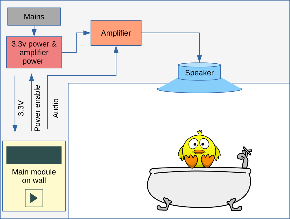
Arrangement of the major components
In addition to the main functionality, I’m also including a clock and temperature/humidity sensor for display when not in use.
Top-level design
Per the above diagram, there are two main components that need to be made - the in-wall module, and the amplifier power switch. I’ll be using a pre-built amplifier and speaker.
Here’s the detailed system design showing all of the major components:
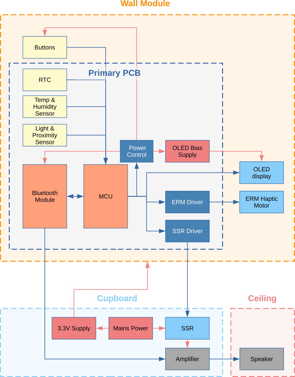
Major components of the system
Bluetooth Module
I reviewed the specs. of several BT audio modules online and finalized on the Microchip (formerly Roving Networks) RN52. I chose it as it seemingly fulfilled my requirements (analog and digital audio output, metadata availability, integrated antenna, etc.) and had a reasonably positive reception online. I did so despite the horrifically brief documentation and fact that it can only be controlled via UART.
The module turned out to be a bit of a headache, which is further elaborated on in the firmware post.
RTC (RV-8803)
I’ve used the RV-8803 on other projects. It’s a great device. It will keep time to within +/- 90 seconds a year (+/- 3ppm) over a temperature range of 40 to +85°C and uses 240 nA @ 3V. That’s about 114 years out of a CR2032 coin cell.
Environmental sensors (BME280)
I had several BME280s left over from another project (aircon humidity control) and thus they became the sensor for this project. In hindsight I should have used a dedicated temperature sensor, as the BME280 doesn’t produce a very accurate temperature reading and this was compounded by the sensor placement.
Adaptive brightness and proximity sensing (VCNL4200)
An ambient light sensor is included to adjust the display brightness based on ambient light levels. The sensor is the VCNL4200, which also incorporates an integrated, long-distance proximity sensor. The proximity sensor will be used to wake the module from an ultra low-power sleep state, to a connectable state that displays the time and temperature.
Display (SH1122)
I chose the largest, highest resolution, white OLED panel that would fit in a standard elecrical box (~80mm). That turned out to be a 2.08", 4-bit, 256x64 pixel display with the SH1122 driver. It cost about US$8
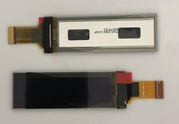
4-bit 256x64 white OLED display (SH1122)
I’ve never used this device before, but a quick review of the datasheet [PDF] showed it to be quite typical. It includes a full frame buffer and variety of available interfaces including SPI, I2C, 8-bit 6800, and 8-bit 8080. I’ll be using SPI.
4-bit Displays Require Read Access for Partial Updates
It’s worth pointing out that if you are not using a separate frame buffer (I am), then you need to use one of the other interfaces on this device, as SRAM read operations are not supported over SPI.
The reason for this is that as a 4-bit display, the number of pixels is > the number of bytes. Since a byte is the minimum writeable chunk, it’s necessary to know what’s already on the screen (i.e. in display RAM) if you want to write individual pixels (which are half of a byte) without overwriting the adjacent one.
This is a non-issue for me, as I’ll be drawing to a full frame buffer in the MCUs SRAM, and then copying the buffer in a single operation. This also simplifies the writing of the driver, as the only operation required (aside from initialization and brightness control) is a full SRAM write.
Update:
When it came time to order a second display (I’m building two devices), I had trouble sourcing the same SH1122 display. I ultimately purchased an identical panel with SSD1362 driving IC and wrote a second driver.
Input and other output
There will be 5 buttons for control:
- Previous track
- Next track
- Play
- Volume up
- Volume down.
I intend to use capacitive buttons, so I’m adding some haptic feedback on button press by way of a small eccentric rotating mass (ERM) motor.
MCU Requirements
Buses
| Type | Number | Devices |
|---|---|---|
| SPI | 1 | SH1122 display |
| I2C | 1 | BME280 sensor, VCNL4200 sensor, RV-8803 RTC |
| UART | 2 | RN52 & debug |
GPIO
| Element | Type | Lines | |
|---|---|---|---|
| Display | output | 3 | (CS, reset, CMD) |
| Power control | output | 3 | (RN52/display, amp, buttons) |
| ERM | output | 1 | |
| LED | output | 1 | |
| Buttons | input interrupt | 5 | |
| Proximity | input interrupt | 1 | |
| RN52 | input interrupt | 1 | |
| RTC | input interrupt | 1 | |
| 16 | (incl. 8 interrupt lines) |
RAM
Outside of the display, RAM requirements are minimal. A full buffer for the screen is 8192 bytes (=256\*64/2). Throw in another few kB for other data and stack, and anything over 10kB is likely to be sufficient.
FLASH
I’m using a decent amount of graphics in the UI, including some animations, which will likely require >10-15kB of space. A 2-bpp, 14pt, ASCII font adds ~ 5kB.
64kb of flash will leave plenty of room for code and other static data.
Power
The device is mains powered, so aside from general power consumption minimization, there are no specific requirements here.
The STMF103C8T6 Suits
Much of my existing library code is for the STMF1xx series and given that it meets all of the above requirements, it was an easy choice. The STM32 universe can be confusing at the best of times, so I created this page to simplify things.
Based on the SRAM, FLASH, and GPIO/Bus requirements, the 48-pin LQFP STMF103C8T6 suits.
Power Requirements
The first step of the power supply design is to check the requirements of the individual components:
| Vmin | Vmax | Imax | |
|---|---|---|---|
| STM32F103xx MCU | 2.0 | 3.6 | 50mA1 |
| RN52 Bluetooth module | 1.8 | 3.6 | 30mA typical |
| OLED display - SH1122 | 1.7 | 3.5 | <500μA |
| OLED display - panel | 7.0 | 14.0 | 30mA2 |
| Amp. power control SSR | 3.0 | 32.0 | 5 - 20mA |
| VCNL4200 light/proximity sensor Vdd | 2.5 | 3.6 | 350μA |
| VCNL4200 light/proximity sensor LED | 3.8 | 5.5 | 550mA3 |
| RV-8803-C7 RTC | 1.5 | 5.5 | <1μA |
| Touch switches (5) | 2.7 | 6.0 | 7.0mA (touched) |
| Haptic motor | 2.0 | 3.5 | 50-85mA |
1 Excluding GPIO source/sink.
2 20mA @ ~66% boost converter efficiency.
3 This is the estimated peak instantaneous current with a 1.8Ω series resistor and 3.3V LED supply.
Minimizing power ICs
The initial plan was to use an external 5V supply, with a 3.3V regulator on the PCB. The reason for this was that SSRs typically need >3.3VDC input voltage and the minimum voltage for the VCNL4200 IR LED is specified in the datasheet as 3.8V.
Upon looking closer at the VCNL4200 architecture though, I couldn’t understand why a lower voltage for the LED wasn’t possible. The reference circuit uses an external PMOS FET to switch the LED, with the LED_CATHODE triggering the FET. The circuit shows a 1k pullup on the gate, suggesting that the LED_CATHODE pin is high-Z when off, and sinks when on. If this is the case, there shouldn’t be any issue using a lower voltage, since the LED’s Vfwd at its Ifwd maximum of 800mA is 2.5V.
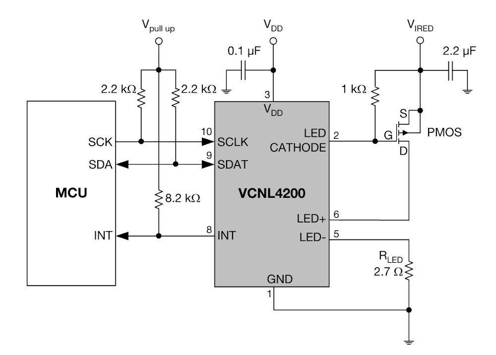
VCNL4200 reference circuit from the datasheet.
source: Vishay
A quick email to Vishay support clarified that 3.8V is not a minimum, and that the part will happily use 3.3V with a suitable resistor to determine the LED current.
The SSR was also a non-issue, as if I couldn’t locate a suitable SSR that worked at 3.3V, I could use the 8.0V output of the OLED bias power supply, since the screen is always on when the amp. is on (edit: actually the amp isn’t on whent the screen is in standby clock mode, but I decided to use a relay anyway).
The simpler route was therefore to use an encapsulated, isolated 3.3V external suppply.
Maximum average current requirement =
    30 (RN52)
  + 50 (MCU)
  + 30 (OLED)
  + 19 (VCNL4200)
  + 10 (SSR)
  + 60 (Haptic)
  + 35 (Touch buttons - all buttons pressed)
  + 10 (PCB LED)
= 245mA (577mA peak when IR LED on = 245 - 18 + 350)
VCNL4200 power requirement calculations
The maximum allowable IR LED pulse current is 800mA. Our accuracy and detection range requirements are modest, so we’re using 350mA moderate, so we’re using 600mA.
The datasheet IR LED IF vs. VF plot gives a forward voltage of ~2.3V at 600mA. The FET has a RDS(on) of around 100mΩ at this current and VGS:
Vfet = 0.1Ω * 600mA = 60mV
Vled = 2.3V
Vresistor = 3.3V - 60mV - 2.3V = 0.94V
R = V/I = 0.94V / 600mA = ~1.6Ω
I only have a 1.8Ω resistor, so I’m using that, which gives a LED current of ~550mA
The maximum duty cycle is 1/160 (min = 1/1280), giving a ~3.4mA average in single pulse mode. This increases linearly with increased pulses/sample up to 28mA in 8 pulse mode.
The standard pulse duration is 30μS, but may be increased up to 270μS. The duty cycle adjusts in proportion, leaving average current unchanged.
Power states
| prox | disp | rn52 | btns | amp | |
|---|---|---|---|---|---|
| sleep | on | - | - | - | - |
| connectable | on | on | on | on | - |
| connected | on | on | on | on | on |
Transitions
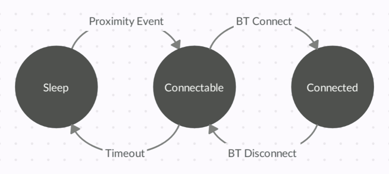
The proximity sensor and connection with external devices drive the state transitions.
Power Consumption in Sleep Mode
| MCU | stop mode | ~20μA |
| TLV755 | no load | 250μA |
| RN52 | disconnected | 0 |
| MCP1661 | disconnected | 0 |
| OLED - panel | disconnected | 0 |
| OLED - SH1122 | sleep | 5μA |
| VCNL4200 | 1/1280 duty | ~2mA |
The proximity sensor consumption could be reduced significantly by running it in manual mode and triggering a reading at a much reduced duty cycle, but this would involve waking the MCU for each measurement. Given the no-load consumption of the power supply is ~23mA (see below), I didn’t think it was worth the added software complexity.
Ultra efficient no-load supplies are hard to come by
Given the low power consumption of the system when in the sleeping state (~2mA), I was keen to find a supply with minimal no-load current draw.
There are various zero consumption no-load reference designs online from all the major semiconductors makers (e.g. see here and here [PDF] ), but I was unable to locate a module type product for sale.
The best I could find at a reasonable price is the Mean Well IRM-03-3.3 3.3 Volt, 3 Watt (900mA) supply. With no load, it consumes <75mW (<23mA), which is not ideal, but is acceptable.
At 75mW, it will use a killowatt-hour of electricity every ~1.5 years.
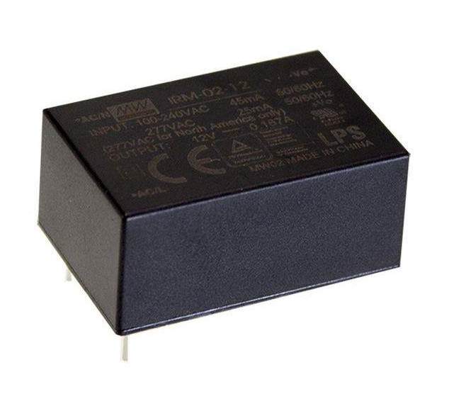
Mean Well IRM-03-3.3 3.3V encapsulated power supply
Switching the amplifier
SSRs, fake SSRs, and fires
The Web is awash with stories of fake Fotek SSRs. Fotek are a legitimate manufacturer of quality SSRs. Perhaps because of this, they seem to be the number one target of counterfeiters.
Various teardowns show the majority to be of fair construction, but massively overrated, using lower-amperage parts and PCB design on devices spec’ed for higher currents. The end result is a literal meltdown and possibly a fire if they are pushed near their specs, as the TRIAC will typically fail closed.
Identifying a legitimate part is very difficult. My strategy is to go for manufacturers that are decent, but without the necessary marketshare to interest counterfeiters. Buying from a reputable source also helps. That’s why I’m using a Delixi 40A SSR sourced from LCSC (~US$6) together with 3A fuse for this project. An equivalent part on Digikey would cost >US$20.
The 3A fuse is used because I won’t be adding a heatsink and thus need to ensure that the SSR doesn’t produce too much heat inside it’s plastic enclosure. Besides which, for this application 720W is well, well beyond what is required by the amplifier. I tested the SSR running at 5A continuously and the heat dissipation is minimal.
Edit:
After additional consideration, I opted to use a traditional relay. I dislike the audible clicking on switching, which is why I initially planned for an SSR, but given the low power requirements, very infrequent switching, and lower heat dissipation, a traditional relay seemed more appropriate. I’m using the 12A Relpol RM50N with 3V coil voltage. I’ll save the Delixis for another project.
Connectors
Connectors from the usual suspects (Digikey, Mouser, Avnet, RS etc.) are some of the more overpriced items for hobby projects.
PCB
For PCB connection, I usually use PH (JST) 2.0mm connectors for signals and KF2510 (or Molex KK254) for power, as versions can be obtained very cheaply in quantity (<USD0.01) from Chinese retailers.
FPC
The OLED screen uses a 31-pin 0.3mm pitch FPC connector. Because the FPC socket will be on the top side of the PCB (the FPC cable is not long enough to reach the bottom), a socket with top contacts was needed. I chose the Panasonic AYF333135 as they were available for ~USD0.15/piece from a local supplier.


