

My attempt to develop custom firmware for the Aqara E1 Zigbee wall switch necessitated learning NXP’s Zigbee SDK for the JN5189.
Below is a brief overview of how applications are structured in the SDK, as well as the key documents that assist with development. It assumes a basic knowledge of Zigbee application structure.
This is not a tutorial. These are my notes as I progressed through the learning process using the JN-AN-1243 example (Zigbee 3.0 Base Device) as a base to develop a device with several endpoints.
You’ll find a similar set of notes on the TI Z-Stack SDK here (link coming soon).
First impression: Much more inviting than the TI Zigbee stack
Having some limited experience with the Texas Instruments CC2652 and its SDK, the JN5189 was a (relatively) pleasant surprise. Despite some initial difficulties getting everything working, the SDK documentation and example programs structure were both more accessible and of higher quality than that of the ZStack. I wrote a separate post discussing the key differences between the NXP and TI approach and why I prefer NXP’s (link coming soon).
Note:
- Most of the discussion here is based on the JN-AN-1243 example. Structure and folder locations etc. will differ with other examples.
- Be sure to use the same SDK version as listed in the examples, as NXP are known to make breaking changes even in patch versions. I’m using
2.6.15.
Key documents
These are the key documents you need to familiarize yourself with:
| Zigbee 3.0 Getting Started [AN1260] |
|
| Zigbee 3.0 Stack User Guide [JN-UG-3130] |
|
| Zigbee 3.0 Devices User Guide [JN-UG-3131] |
Zigbee device (i.e. BDB/ZLO/ZDO/ZCL) development reference. This document provides more specific guidance on developing Zigbee ZLO and ZCL applications, including sections on each device type. |
| Zigbee Cluster Library [JN-UG-3132] |
Documentation or the ZCL layer of the SDK. This is the main API for typical ZCL applications like lights, sensors, switches etc. |
| MCUXpresso SDK API Reference Manual | Reference for core low-level peripheral APIs and some higher-level bus drivers. |
Connectivity Framework Reference Manual (get from the SDK as the version online at the NXP site is >9 years old.) |
The Connectivity Framework provides typical OS services such as scheduling, synchronization primitives and messaging, memory management, device APIs (e.g. timers, flash, keyboards, buttons, LEDs etc.), etc. It is independent of any wireless SDK in use (e.g. Zigbee, BLE) and also provides an abstraction layer over any OS (FreeRTOS). |
| JN518x/K32W041/K32W061/K32W1 Core Utilities User Guide | The Core Utilities (JCU) provides drivers for persistent data (flash), power management, and debug logging. Apparently this functionality has been migrated to the Connectivity Framework and these utilities are only intended for legacy applications UPDATE: persistent storage on some devices (including the JN5189) uses the Persistent Data Manager (PDM) component. This is part of the Core Utilities. |
| ZigBee 3.0 Green Power User Guide [JN-UG-3134] |
Green Power functionality |
Getting the documentation
After using the MCUXpresso SDK Builder (on the NXP website) to download the SDK Archive and installing it into the IDE, you would be forgiven for expecting the SDK docs folder to include all of the core documentation. Although it contains most of it, for some reason the Zigbee 3.0 Getting Started document and the MCUXpresso SDK API Reference Manual are not included. You need to also select the Download SDK Documentation from the SDK builder. This package contains all of the docs in the SDK Archive, plus the aforementioned missing ones.
Zigbee example programs
The SDK includes basic examples for a coordinator, router, and end device. The SDK document ZBEXDK006UG - ZigBee Demo Applications Users Guide details how to run these. I didn’t try them and so can’t comment.
The majority of the Zigbee examples are distributed as applications notes. For these, the Zigbee 3.0 Getting Started document is key. The standard MCUXpresso installation will not build the Zigbee samples. Additional steps are required and are explained in this document. Also, if you’re using Linux, then various changes are needed. Check out this post for instructions on how to setup things up:
NXP Zigbee development on Linux
Drivers and supporting code
-
[SDK]/devices/JN5189/drivers- Low-level peripheral drivers - e.g. DMA, power, SPI/I2C/USART, clock, flash etc. (
fsl_*naming) - Documented in the MCUXpresso SDK API Reference Manual
- Examples in
[SDK]/boards/jn5189dk6/driver_examples(also available within the IDE)
- Low-level peripheral drivers - e.g. DMA, power, SPI/I2C/USART, clock, flash etc. (
-
[SDK]/middleware/wireless/framework- Connectivity framework drivers / utilities / OS abstraction source
- Documented in the Connectivity Framework Reference Manual
-
[SDK]/middleware/wireless/zigbee- BDB, ZCL (ZCL, ZHA, ZGP), etc. Zigbee application layer source
- Documented in the Zigbee 3.0 Stack User Guide
The Connectivity Framework
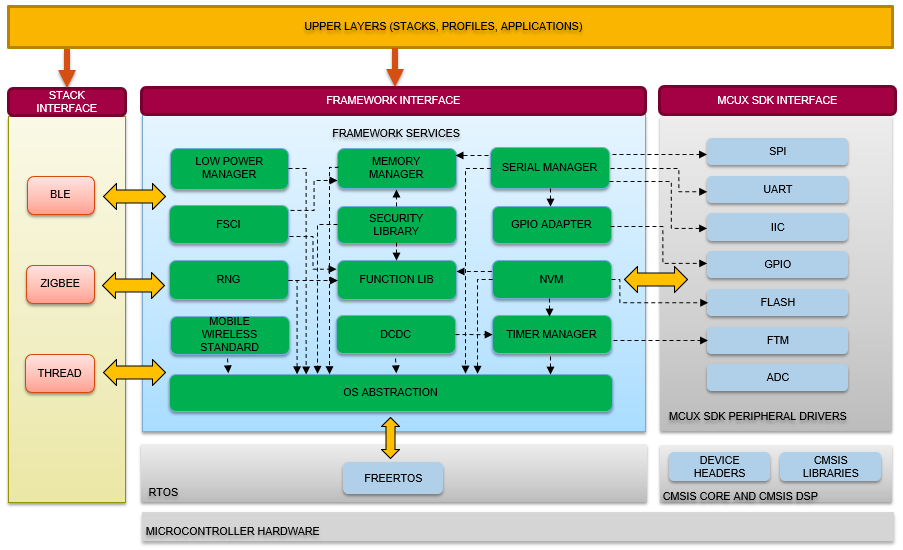
Connectivity framework integration
Image courtesy of NXP
Where’s the entry point?
I was initially confused as to how the examples actually ran. The samples contain no main function, just main_task, which looked very much like an RTOS task function, but with no RTOS to be found.
The Zigbee SDK docs (spread across three documents - reference, intro to Zigbee, Zigbee apps) are very Zigbee API focused and don’t cover the higher level application lifecycle.
A little digging revealed that the Wireless Connectivity Framework handles application startup. The user application interfaces with an OS abstraction layer, which in turn interfaces with an OS (if present) or in the case of this example, a very simple bare metal scheduler.
The Connectivity Framework provides typical OS services such as scheduling, synchronization primitives and messaging, memory management, device APIs (e.g. timers, flash, keyboards, buttons, LEDs etc.), etc.
It is independent of any wireless SDK in use (e.g. Zigbee, BLE) and also provides an abstraction layer over any OS in use (FreeRTOS).
int main is defined in:
SDK_ROOT/middleware/wireless/framework/OSAbstraction/Source/fsl_os_abstraction_bm.c
fsl_os_abstraction_bm.c
int main (void)
{
  OSA_Init();
  /* Initialize MCU clock */
  hardware_init();
  OSA_TimeInit();
  OSA_TaskCreate(OSA_TASK(main_task),NULL);
  OSA_Start();
  return 0;
}
The application is responsible for implementing hardware_init and main_task. All of this is explained in the Wireless Connectivity Framework manual.
General application flow
Below is the basic call tree flowing from hardware_init and main_task in JN-AN-1243, which provides Basic Device Behavior (BDB) as Coordinator, Router, or End Device.
There are various defines that affect compilation. This example is for the Router configured as GP Proxy with watchdog, but without NFC support. Build target is the JN5189.
hardware_init in app_start.c - pseudocode
- APP_vSetupHardware
  - enable DMA access to RAM
  - BOARD_InitHardware
    - POWER_Init
    - reset FLEXCOMM for USART (RESET_PeripheralReset)
    - enable watchdog reset
    - BOARD_InitClocks
    - BOARD_InitDebugConsole
    - BOARD_InitPins

  - CLOCK_EnableAPBBridge
  - Start crystal (CLOCK_EnableClock)
  - Initialize LED GPIOs (GPIO_PinInit)
  - Setup and initialize watchdog
  - Set interrupt priorities
  - SystemCoreClockUpdate
  - OSA_TimeInit
main_task in app_main.c - pseudocode
- Initialize on first call
    - SecLib_Init                                    // Init crypto HW accel
    - RNG_Init                                       // Init RNG software module
    - MEM_Init                                       // Init memory manager
    - TMR_Init                                       // Init timer module

    - vAppMain                                       // [app_start.c]
                                                     // -------------------
        - vDebugExceptionHandlersInitialise          // [Exceptions_NVIC.c]
        - halt if reset was due to watchdog

        - APP_vInitResources                         // [app_start.c]
                                                     // -------------------
            - ZTIMER_eInit                           // init Z timer module
            - create timers (ZTIMER_eOpen)           // create pwr, button, ZCL timers
            - create queues (ZQ_vQueueCreate)        // create app, bdb, timer etc. event queues

        - APP_vInitialise                            // [app_start.c]
                                                     // -------------------
            - PWR_init                               // init power manager
            - PWR_vForceRadioRetention               // force radio registers retained in sleep
            - PDM_eInitialise                        // init PDM (NV) module
            - PDUM_vInit                             // init app PDM (NV)
            - ZPS_vExtendedStatusSetCallback         // set callback for stack extended error situation
            - APP_vRadioTempUpdate                   // init radio temp reporting [app_start.c]

            - APP_vInitialiseRouter                  // [app_router_node.c]
                                                     // -------------------
                - vManagePowerOnCountLoadRecord      //
                - vAPP_GP_LoadPDMData                // load GP data from NV        [app_green_power.c]
                - PWR_DisallowDeviceToSleep          // disable sleep since this is the router
                - PDM_eReadDataFromRecord            // read node info from NV
                - eRestoreReports                    // load attr reports from NV
                - ZPS_eAplAfInit                     // init ZBPro stack
                - APP_ZCL_vInitialise                // init ZCL related functions  [app_zcl_task.c]
                - APP_vBdbInit                       // init BDB attr and msg queue [app_router_node.c]
                - APP_vLedInitialise                 // init LEDs                   [app_leds.c]
                - APP_bButtonInitialise              // init buttons                [app_buttons.c]

                - vLoadDefaultConfigForReportable    // load attr reporting defaults if load from NV failed
                - vMakeSupportedAttributesReportable // make on/off/levelCtrl attr reportable
                - vPrintAPSTable
                - vManagePowerOnCountInit
            - BDB_vStart                             // perform BDB init procedure
            - SystemCoreClockUpdate                  // calc current clock from registers [system_JN5189.c]
            - OSA_TimeInit                           //
- Loop
    - zps_task_ZPS                                   // process ZPS events
    - bdb_taskBDB                                    // process events from the BDB queue
    - ZTIMER_vTask                                   // process timers, callbacks
    - APP_taskRouter                                 // process app related events [app_router_node.c]
    - WWDT_Refresh (watchdog)                        // kick the watchdog
    - PWR_EnterLowPower | PWRM_vManagePower          // ??
    - break loop if !RTOS                            // Non-RTOS can't preempt so break
                                                     // and main_task will be called again
Key Zigbee files
app_main.c |
Entry point |
bdb_options.h |
BDB settings (e.g. channels, commissioning modes etc.) |
zcl_options.h |
Which clusters to enable, cluster attribute values. |
app_zcl_task.c |
ZCL initialization and main ZCL event handler (APP_ZCL_vEventHandler).Events are received here and dispatched to the stack, which then calls back to other handlers in the same file. |
app_router_node.c* |
BDB event handler, APP event handler, AF event handler, ZDO event handler |
Event handling
There are three/four (main) entry points for Zigbee event handling in the application:
1. APP_vBdbCallback             [from stack] | fixed name
   -> vAppHandleAfEvent
      -> APP_ZCL_vEventHandler
      -> vAppHandleZdoEvents

2. APP_ZCL_cbGeneralCallback    [from stack] | registered by app via eZCL_Initialise

3.  APP_ZCL_cbEndpointCallback  [from stack] | registered by app via eZHA_RegisterBaseDeviceEndPoint
    -> APP_vHandleClusterUpdate
    -> APP_vHandleClusterCustomCommands


4. APP_ZCL_vEventHandler        [from stack indirectly - see below] | set in zpscfg
                                This function is set in the zpscfg, but it's not clear
                                if it is actually called directly by the stack.
// Timer events

APP_cbTimerZclTick
- [every 100ms]    -> vZCL_EventHandler [SDK]

APP_taskRouter
- [GP timer event] -> vZCL_EventHandler [SDK]

APP_ZCL_vEventHandler
-> [ALL] vZCL_EventHandler [SDK]
APP_taskRouter
- [GP timer event] -> vZCL_EventHandler [SDK]
//
// This function is set as the general ZCL callback on ZCL init
//

SDK -> APP_vBdbCallback
- [BDB_EVENT_ZPSAF]                 -> vAppHandleAfEvent
- [BDB_EVENT_INIT_SUCCESS]          -> PDM_eSaveRecordData
- [BDB_EVENT_NWK_FORMATION_SUCCESS] -> PDM_eSaveRecordData
- [BDB_EVENT_NO_NETWORK]            -> BDB_eNsStartNwkSteering
- [BDB_EVENT_NWK_STEERING_SUCCESS]  -> PDM_eSaveRecordData

//
// This function is set as the general ZCL callback on ZCL init
//

SDK -> APP_ZCL_cbGeneralCallback
- no processing, just log

//
// This function is set as callback when registering each EP
//

SDK -> APP_ZCL_cbEndpointCallback
- [E_ZCL_CBET_CLUSTER_CUSTOM]                         -> APP_vHandleClusterCustomCommands
- [E_ZCL_CBET_CLUSTER_UPDATE]                         -> APP_vHandleClusterUpdate
- [E_ZCL_CBET_REPORT_INDIVIDUAL_ATTRIBUTES_CONFIGURE] -> vSaveReportableRecord
These three functions are called by the stack, and the dispatch messages to various other handlers. There are also tick handlers for the various timers started in APP_vInitResources. There are also various other functions that are called by name from the ZCL source code and other places.
Main event handling functions
| app_router_node.c* | |
APP_vBdbCallback |
This is the main handler for stack events. |
vAppHandleAfEvent |
Handles AF events dispatched from APP_vBdbCallback. |
vAppHandleZdoEvents |
Handles ZDO events dispatched from vAppHandleAfEvent |
APP_taskRouter |
Process pending app events - called from main app loop |
| app_zcl_task.c | |
APP_cbTimerZclTick |
Callback for ZCL timer |
APP_cbTimerGPZclTick |
Callback for GP timer |
vIdEffectTick |
Tick for ZCL identify (APP_cbTimerZclTick->eZCL_Update100mS->vIdEffectTick) |
APP_ZCL_vEventHandler |
Handles ZCL events dispatched from vAppHandleAfEvent. Events are passed back to the stack here, actioned by the stack, and delivered to more specific callbacks????. |
APP_ZCL_cbGeneralCallback |
Callback from stack. Set in call to eZCL_Initialise |
APP_ZCL_cbEndpointCallback |
Callback from stack for endpoint events. Set in call to endpoint init function (e.g. eZHA_RegisterBaseDeviceEndPoint) |
APP_vHandleClusterUpdate |
Handles cluster update events (attribute changed) dispatched from APP_ZCL_cbEndpointCallback |
APP_vHandleClusterCustomCommands |
Handles custom cluster events dispatched from APP_ZCL_cbEndpointCallback |
APP_vHandleClusterUpdate: Called when something on the local node causes any attribute to be changed APP_vHandleClusterCustomCommands = message defined in a cluster
* Filename varies across examples.
App loop
`main_task` loop
-> `zps_taskZPS`     [stack]
-> `bdb_taskBDB`     [stack]
-> `ZTIMER_vTask`    [stack]
-> `APP_taskRouter` - handle app events
-> `WWDT_Refresh`
-> `PWR_EnterLowPower` | `PWRM_vManagePower`
Code generation
The SDK uses code generation tools to simplify the Zigbee configuration process. All Zigbee related configuration data is stored in an XML file named /Common/Source/app.zpscfg. This file is edited in the IDE with the ZBPro Configuration Editor plugin (requires manual installation per the setup document discussed above). During the build, Python scripts generate source files based on the configuration file contents.
ZPSConfig
[SDK]/middleware/wireless/zigbee/tools/ZPSConfig/Source/ZPSConfig
-> /Router/Source/zps_gen.h
-> /Router/Source/zps_gen.c
PDUMConfig
[SDK]/middleware/wireless/zigbee/tools/PDUMConfig/Source/PDUMConfig
-> /Router/Source/pdum_gen.h
-> /Router/Source/pdum_gen.c
Project structure
Unlike the TI ZStack setup (Link coming soon), SDK files that are included in the build are not linked in the IDE project explorer. This helps make clear the separation between the application and the SDK, but also makes browsing and searching the source more difficult.
Build system
The projects use a standard make process rather than Eclipse CDT’s managed build. There is a base makefile for each build configuration, which includes others depending on the configuration.
The makefile for the Router build configuration is in the project at Router/Build/mcux/Makefile. There are several others within the router section:
Router/Build/mcux/k32w0BuildConfig/ZBPro/Build/config_OSA.mkRouter/Build/mcux/k32w0BuildConfig/ZBPro/Build/config_ZBPro.mkRouter/Build/mcux/k32w0BuildConfig/ZCL/Build/config_ZCL.mk
as well as within the SDK itself - e.g.:
[SDK_BASE_DIR]/middleware/wireless/zigbee/BDB/Build/config.mk[SDK_BASE_DIR]/middleware/wireless/zigbee3.0/BuildConfig/ZCL/Build/config_ZCL.mk
Files are included either from the project or the SDK based on compilation flags.
Much of the build configuration is in the base makefile: e.g. OTA encryption, NTAG, GP proxy type, debug, target chip, PDM type, BDB functionality etc.
Here are the basic steps performed by the Router makefile:
Build process: Router/Build/mcux/Makefile
 1. Set configuration parameters
 2. Set debug flags
 3. Set build folders
 4. Set source files
 5. Include `ZCL.mk` [could be SDK or project specific depending on FRAMEWORK_SWITCH]
    1. Include `ZBPro.mk` [could be SDK or project specific depending on FRAMEWORK_SWITCH]
       1. Add source files for device drivers
       2. Add Zigbee compiled libraries
    2. Include source files for relevant ZCL clusters
    3. Include source files for GP if required
    4. Include includes relevant ZCL clusters
 6. Include SDK `BDB/Build/config.mk`
    1. Add source folders for BDB
    2. Add source files for BDB
    3. Add include folders for BDB
 7. Run code generation tools (ZPSConfig, PDUMConfig, ZPS config etc.) and add generated source files
 8. Compile
 9. Link
10. If encrypted:
    - run JET.exe to create encrypted OTA image
    else
    - run JET.exe to create unencrypted OTA image
11. Cleanup
The keys/config used to build encrypted OTA images are located in the Makefile and at:
Router/Build/mcux/LinkKey_HA.txt, Router/Build/mcux/configOTA_Cer_Keys_HA.txt
Debug logging
Basic serial debug logging (and input) is provided by the MCUXpresso SDK and is located in the devices/JN5189/utilities/debug_console folder.
Note that the SDK reference manual is included in the separate docs package on the NXP SDK Builder. It is not available in the docs folder of the main SDK download.
The main logging function is DbgConsole_Printf. It’s available to call directly, but is also aliased by the PRINTF macro, which resolves to nothing (empty do while) when disabled (SDK_DEBUGCONSOLE == DEBUGCONSOLE_DISABLE).
The Connectivity Framework provides alternate macros, but they’re not documented*, which is odd given that they’re used in all of the sample applications. They are in wireless/framework/dbg.h.
The key macros are DBG_vAssert and DBG_vPrintf, which despite the names, don’t accept a va_list (it’s actually Hungarian notation showing that the return type is void).
For non JN518x chips, the macros take care to evaluate the provided arguments even when debugging is disabled. When enabled, they delegate to a bunch of functions that are presumably defined in other SDKs or by the user (e.g. dbg_vPrintfImplNoneVerbose).
For JN518x chips, they delegate to the PRINTF macro mentioned above when the first provided argument is true, but don’t evaluate other arguments when not.
* Update:
I did find documentation for them in the 2016 N51xx Core Utilities User Guide (JN-UG-3116), which is surely out of scope for the 5189, since the chip wasn’t released then. So presumably DBG_vPrintf was part of the “core utilities”, which are deprecated in favor of the Connectivity Framework.
DBG_vPrintflogging was part of the 5169/5179 Core Utilities and was documented there.- Core Utilities were deprecated in favor of the Connectivity Framework after the JN5189 release
- The Connectivity Framework doesn’t include logging
- Logging is included in the MCUXpresso SDK
File level enable/disable
This allows for file level debug en/disabling via the first parameter to DBG_vPrintf while still allowing for full disabling with SDK_DEBUGCONSOLE == DEBUGCONSOLE_DISABLE.
port_JN518x.c?
It’s worth mentioning that DbgConsole_Printf is defined in both fsl_debug_console.c and middleware/wireless/zigbee/ZigbeeCommon/Source/port_JN518x.c. This latter file is not included in the build of the example program I’ve been working with. It also includes implementations for various synchronization primitives and a definition for DBG_vInit. This function is declared in dbg.h, but not defined or called anywhere else or in the samples.
Perhaps it’s a work in progress. More likely the samples haven’t been updated for changes in the SDK.
Debug logging - TLDR
For the JN5189, use DBG_vPrintf and DBG_vAssert.
This is in effect DBG_vPrintf -> PRINTF -> DbgConsole_Printf.
Modifying the examples
The JN-AN-1243 example only implements BDB. That is, functionality for forming, joining, and maintaining the network, GP proxy, attribute reporting, binding, and service discovery. For a useful ZCL application, it’s necessary to add additional endpoints and clusters.
When compiled as a router, the example also implements the onOff cluster (ZCL cluster 0x0006) as a server. This server cluster (i.e. receives commands from a client) is typically used for devices with an onOff output such as a light or relay switch.
How about some C++?
In short, the SDK is not well setup for C++ development. You can make it work, but it’s tedious. So much so that a description of the process required it’s own article:
Using C++ with the NXP Zigbee SDK
Uploading firmware
The SDK includes the DK6Programmer, which is a Windows-only executable that programs the JN5189 via ISP. The device must be manually put into ISP mode first by resetting with the relevant pin held low.
My development platform is Linux, but I had no problem using the tool with a Windows VM and standard USB<->UART adapter.
I also have an OM15080 JN5189 USB stick, which includes an FT230X. The DK6 programmer helpfully puts the device into ISP automatically via the BitBang mode of the FT230X before programming.
Debugging
My exposure to the JN5189 is in the context of rewriting firmware for the Aqara E1 light switch. The debug interface of the chip is not readily available on the PCB and so I have no experience with it. I believe probes such as NXP MCU-Link, Segger J-Link, PE Micro Cyclone etc. are all compatible. The NXP evaluation board has a built-in “Link2” probe.
OTA updates
I have yet to test OTA image update functionality. The SDK has full support, and the example makefiles include scripts to generate encrypted images. The tools are Windows-only.
Update: I wrote a full article on the NXP Zigbee SDK OTA Update functionality.
SDK problems
There are a bunch of issues with the SDK. Some that frustrated me are:
The docs don’t contain tables of contents.
Some do (often at the end), but docs like the 888-page JN5189 User Manual, do not. They have PDF indices, but it’s not really a suitable substitute.
It relies on many specifically-named functions to be present in your application and most of them are not documented.
Although some callback functions are registered explicitly (e.g. ZCL callback function passed in eZCL_Initialise), the vast majority are just expected to be present by name.
There are various functions defined in the samples that are seemingly unused. It’s only after searching the SDK source that you find that they’re called from the middle of the ZCL SDK.
So parts of the samples are effectively a part of the SDK. A typical example is the vSaveScenesNVM function, which is present in the samples with scenes functionality. This function is called by name from the SDK scenes and groups clusters ZCL source code, but is completely undocumented in the ZCL and Zigbee API docs.
The usual approach would be to pass a pointer to the eCLD_ScenesCreateScenes function, which sets up the cluster and already requires a bunch app-level data passed. Omitting it possibly saves a function pointer’s worth of RAM (although I suspect any decent optimizing compiler should be able to eliminate that anyway), but makes the API far more opaque.
Inconsistent naming, parameter order etc.
Simple things like changing the order of flags in functions within the same file / API.
Take eZCL_SetReportableFlag and eZCL_CreateLocalReport for example, which are typically called one after the other and have an identical parameters first 4 parameters, except the order of the two boolean flags (bIsServerClusterInstance and bIsManufacturerSpecific) are reversed:
eZCL_SetReportableFlag(1, 2, TRUE, FALSE...);
eZCL_CreateLocalReport(1, 2, FALSE, TRUE...);
Variable and parameter naming could also use some work. For example many functions require you to specify message direction as going form server->client or client->server.
/**
  * bool_t bDirection From Client/Server
  */
teZCL_Status eZCL_CustomCommandSend(... bool_t bDirection ... )
If forced to guess, I would have thought that true is From Client->Server, but it could also mean false/true = From Client/From Server (spoiler alert - this is what it means). Any sane developer would name it bDirFromServer.
Endpoints are sometimes referenced by ID and sometimes by index. Many parameters are suitably named like: u8SourceEndPointId, pu8EndpointIndex, but some are named u8SrcEndPoint, or u8EndPointNumber, leaving us to guess as to whether an index or ID is expected.
Most of the function signature comments seem to have been copied and pasted and often haven’t been updated.
Lots of unnecessary global data
Cluster definitions, attribute definitions etc.
They are all declared extern in their respective headers.
Configuration by preprocessor macros
Support for various server/client clusters is included in the build through the use of copious amounts of macros. This is pretty typical for embedded SDKs.
The problem is that the ZCL code then uses these macros to determine whether to include those clusters in various devices etc. The result is the inability for any fine grained control over which clusters are included when using multiple endpoints.
Endpoints have three different numbering schemes
When endpoints are registered with eZCL_Register, an endpoint definition structure is passed, which includes the u8EndPointNumber member. This member is defined as:
u8EndPointNumber is the endpoint number between 1 and 240 (0 is reserved)
Internally, the ZCL stores endpoints in an array of endpoint structures (psZCL_Common->psZCL_EndPointRecord). They are added here sequentially in order of registration.
To convert between the IDs provided on registration and the internal indices, the undocumented ZCL functions eZCL_SearchForEPIndex / u8ZCL_GetEPIdFromIndex are used.
Finally, endpoint IDs must also be specified in the Zigbee configuration editor. These are output as in zps_gen.c. e.g.:
uint8 au8EpMapPresent[6] = {1, 10, 20, 30, 100, 242 };
Aside from failing the DRY principle, you might have spotted a problem with this approach.
Although we can’t see exactly how this array is used (as it is accessed from the closed source libZPSAPL) it seems safe to assume that it needs to match the order in the psZCL_Common->psZCL_EndPointRecord array mentioned above, which means the order of endpoint registration must match the order of endpoints in the ZPS configuration file.
This doesn’t seem to be documented anywhere and bit me once I started adding extra endpoints for OTA etc.
A simple check in eZCL_Register could avoid problems here:
if (au8EpMapPresent[u8NumberOfRegEndpoints] != psEndPointDefinition->u8EndPointNumber) {
    // ALERT!!!!
}
Index/ID bugs
A more significant problem is the presence of several bugs in the way that the endpoint IDs are handled. Various functions accept an u8SourceEndPointId parameter, but in-fact require the endpoint index, not the ID.
It seems likely that NXP never tested the SDK with non-contiguous endpoints, and so never discovered these bugs. It appears as though the SDK originally only supported sequential endpoint numbers beginning at 1 (ZDO endpoint is 0). At some point it was migrated to IDs, but several functions were never updated.
Here’s an example from the OTA code:
eOtaFindCluster(uint8 u8SourceEndPointId...)
teZCL_Status eOtaFindCluster(uint8 u8SourceEndPointId...)
{
    // WRONG - assumes u8SourceEndPointId is the index, not the ID
    if(u8SourceEndPointId > u8ZCL_GetNumberOfEndpointsRegistered())
    {
        return(E_ZCL_ERR_EP_RANGE);
    }
    ...
}
See below for more examples of this buggy behavior.
Disconnect between ZPS editor and code
All endpoints, clusters etc. must be specified in the ZPS configuration editor. The build uses code generation to produce configuration code for the SDK.
All endpoints are specified, and yet ZCL_NUMBER_OF_ENDPOINTS must still be defined separately.
All clusters are specified, and yet the SDK code must be manually included for every cluster (e.g CLD_ONOFF, ONOFF_SERVER, ONOFF_CLIENT etc. macros)
The documentation is very wrong in places
As an example, the OTA Initialization (49.6) section in JN-UG-3132 states:
49.6 Initialization
Initialization of the various software components used with the OTA Upgrade cluster (see Section 49.5) must be performed in a particular order in the application code. The initialization could be incorporated in a function APP_vInitialise(), as is the case in the NXP ZigBee PRO Application Template (JN-AN-1248).
JN-AN-1248 doesn’t appear to be available anymore. Presumably it was for the previous generation (i.e. JN-5169).
Initialization must be performed in the following order:
The NVM module must first be initialized using the function NvModuleInit().
The persistent data record(s) should then be initialized using the function and registered NVM_RegisterDataSet().
All of the samples use the PDM_* interface, not the NV* functions
- The ZigBee PRO stack must now be started by first calling the function ZPS_vSetOverrideLocalMacAddress() to over-ride the existing MAC address, followed by ZPS_eAplAfInit() to initialize the Application Framework and then ZPS_eAplZdoStartStack() to start the stack.
ZPS_vSetOverrideLocalMacAddress is not documented anywhere in the SDK docs, is not called from any of the samples, and I couldn’t find it in the SDK source. Likely it was used in the older SDK.
ZPS_eAplZdoStartStack is actually called by the BDB function BDB_vStart.
- The ZCL initialization function, eZCL_Initialise(), can now be called. An OTA Upgrade cluster instance should then be created using eOTA_Create(), followed by a call to eOTA_UpdateClientAttributes() or eOTA_RestoreClientData() on a client to initialize the cluster attributes.
eOTA_UpdateClientAttributes and eOTA_RestoreClientData will fail if called before the endpoint has been registered (step 6)
The Flash programming of the OTA Upgrade cluster must now be initialized using the function vOTA_FlashInit().
The required device endpoint(s) can now be registered (for example, a Simple Sensor device).
etc.
The code wastes RAM
RAM is precious in the embedded world. The SDK code fails to declare many read-only variables const, resulting in them occupying RAM when they could be stored in flash. SDK function parameters also lack const specifiers, preventing user data from being made const.
It was necessary to modify many function signatures in the SDK to allow for constexpr payload data etc.
Various structures could be const
Thankfully most clusters’ tsZCL_AttributeDefinition arrays are const, but some are not (e.g [Analog|Binary|Multistate][Input|OutputBasic]). The server/client tsZCL_ClusterDefinition objects for each cluster are also not const. Marking these const in my E1 firmware saved nearly half a kilobyte of RAM.
Basic cluster
Almost every attribute in the Basic cluster is read-only, yet the SDK stores everything in RAM.
Let’s say your product’s serial number is 123456789. You are required to define the size of the data in on of the headers:
#define CLD_BAS_SERIAL_NUMBER_SIZE 9
But then the code allocates CLD_BASIC_MAX_NUMBER_OF_BYTES_SERIAL_NUMBER bytes in RAM:
// Basic.h

#define CLD_BASIC_MAX_NUMBER_OF_BYTES_SERIAL_NUMBER 32
...
// typedef struct
// {
//    uint8    u8MaxLength;
//    uint8    u8Length;
//    uint8   *pu8Data;
// } tsZCL_CharacterString;
tsZCL_CharacterString       sSerialNumber;
uint8                       au8SerialNumber[CLD_BASIC_MAX_NUMBER_OF_BYTES_SERIAL_NUMBER];
You then need to do a memcpy at runtime in the initialization function to copy the static data into au8SerialNumber. The string meta data is initialized when the cluster is initialized like so:
// Basic.c - eCLD_BasicCreateBasic

((tsCLD_Basic*)pvEndPointSharedStructPtr)->sSerialNumber.u8MaxLength = sizeof(((tsCLD_Basic*)pvEndPointSharedStructPtr)->au8SerialNumber);
((tsCLD_Basic*)pvEndPointSharedStructPtr)->sSerialNumber.u8Length = CLD_BAS_SERIAL_NUMBER_SIZE;
((tsCLD_Basic*)pvEndPointSharedStructPtr)->sSerialNumber.pu8Data = ((tsCLD_Basic*)pvEndPointSharedStructPtr)->au8SerialNumber;
I modified the SDK to store a single copy in flash:
#define CLD_BAS_SERIAL_NUMBER_VALUE "123456789"
#define CLD_BAS_SERIAL_NUMBER_SIZE 9
...
// Basic.h

tsZCL_CharacterString       sSerialNumber;
//uint8                       au8SerialNumber[CLD_BASIC_MAX_NUMBER_OF_BYTES_SERIAL_NUMBER];

// Basic.c - eCLD_BasicCreateBasic

// ((tsCLD_Basic*)pvEndPointSharedStructPtr)->sSerialNumber.u8MaxLength = sizeof(((tsCLD_Basic*)pvEndPointSharedStructPtr)->au8SerialNumber);
// ((tsCLD_Basic*)pvEndPointSharedStructPtr)->sSerialNumber.pu8Data = ((tsCLD_Basic*)pvEndPointSharedStructPtr)->au8SerialNumber;
((tsCLD_Basic*)pvEndPointSharedStructPtr)->sSerialNumber.u8MaxLength = CLD_BAS_SERIAL_NUMBER_SIZE;
((tsCLD_Basic*)pvEndPointSharedStructPtr)->sSerialNumber.pu8Data = CLD_BAS_SERIAL_NUMBER_VALUE;
Multiple instances
Also despite all the data being read-only, every ZLO device also has it’s own instance of the basic cluster. It was necessary to also modify the SDK ZCL code to share a single instance.
The ZBPro configuration editor is buggy and (by default) hides details
During my E1 firmware development, I added a new router configuration in the ZBPro configuration editor for the different E1 switch hardware model. I used the copy/paste function provided to copy the existing router node. The copy/paste function itself is a bit buggy and resets some of the destination properties, but those are easily fixed manually.
After building with the new Router node selected (set as a command line param to the ZPSConfig script) and flashing the target, it failed to join any network. Everything else appeared to be working correctly, but it wouldn’t join.
Suspecting the editor, I opened the app.zpscfg file in a text editor and checked the two nodes against each other. I immediately noticed many properties of the node that are not shown in the editor. Despite the copy/paste, some of these differed. Specifically:
- RouteDiscoveryTableSize changed from 4 to 1
- RoutingTableSize changed from 70 vs 60
- apsUseExtPANId changed from
0x0000000000000000to0x1234567887654321
The external PAN ID was clearly the issue, and after reverting it to the correct value and re-flashing, the device promptly joined the network.
Update:
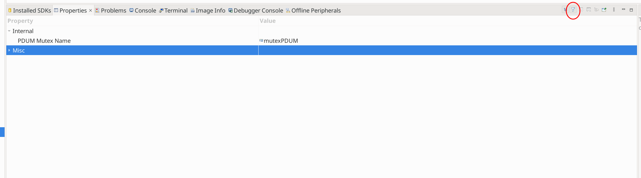
It turns out that these properties can be displayed in the editor by enabling “Advanced Device Parameters”. This is mentioned on page 298 of the ZigBee 3.0 Stack User Guide (rev 4.1), where it makes clear that after selecting the appropriate node, you need to click this button:
Enabling display of advanced properties
Vital information is somewhat hidden in the docs
If you have output clusters on an endpoint without the corresponding input cluster, the stack will silently drop messages destined for that output cluster.
When an endpoint with an output cluster sends data, the receiving endpoint must have an input cluster in order to receive the data, otherwise the stack will reject it and will not notify the receiving endpoint. However, the Default cluster can be added to the endpoint in order to deal with received data that is destined for input clusters not supported by the endpoint (see the Note below this procedure).
…
Note: In the above procedure, you may want to add the Default cluster (with a Cluster ID of 0xFFFF) as an input cluster. The inclusion of the Default cluster means that received messages that were intended for input clusters not supported by the endpoint will still be passed to the application. The messages must, however, come from defined application profiles, otherwise they are discarded.
Zigbee 3.0 Stack User Guide
Page 297
There are serious bugs in the SDK endpoint ID/index treatment
A mentioned briefly above, there are various places in the SDK source that assume that all endpoint IDs are contiguous and begin at 1.
eCLD_OnOffUpdate accepts an endpoint ID (not index):
/****************************************************************************
 ** NAME:       eCLD_OnOffUpdate
 ** uint8                       u8SourceEndPointId          Source EP Id
 ****************************************************************************/

teZCL_Status eCLD_OnOffUpdate(uint8 u8SourceEndPointId);
As does eCLD_LevelControlUpdate, eCLD_ScenesUpdate, and eCLD_ColourControlUpdate.
eZCL_Update100mS is a function called by the ZCL timer, which calls all of these functions, but passes an index beginning at, not endpoint IDs:
teZCL_Status eZCL_Update100mS(void)
{
    /* Update clusters on each end point if any */
    #if ((defined LEVEL_CONTROL_SERVER) || (defined SCENES_SERVER) || \
         (defined COLOUR_CONTROL_SERVER)|| (defined ONOFF_SERVER) || \
         (defined IDENTIFY_SERVER) )
        {
            uint8 u8NumEndpoints;
            u8NumEndpoints = u8ZCL_GetNumberOfEndpointsRegistered();

            int i;
            for (i = 1; i < (u8NumEndpoints + 1); i++)
            {
                #if (defined LEVEL_CONTROL_SERVER)
                    eCLD_LevelControlUpdate(i);
                #endif

                #if (defined SCENES_SERVER)
                    eCLD_ScenesUpdate(i);
                #endif

                #if (defined COLOUR_CONTROL_SERVER)
                    eCLD_ColourControlUpdate(i);
                #endif

                #if (defined ONOFF_SERVER) && (defined CLD_ONOFF_CMD_ON_WITH_TIMED_OFF)
                    eCLD_OnOffUpdate(i);
                #endif

                #if (defined IDENTIFY_SERVER) && (defined CLD_IDENTIFY_10HZ_TICK)
                    vIdEffectTick(i);
                #endif
            }
        }
    #endif
    return E_ZCL_SUCCESS;
}
Similar bugs are present in the OTA handling code, as well as the finding and binding code.