
This is the first part of a five-part post detailing the design and implementation of new firmware for the Aqara E1 Zigbee light switches:
- Replacing the firmware in the Aqara E1 light switch
- Reverse engineering the PCB
- Planned new firmware features
- Writing new firmware
- Zigbee2MQTT, the NXP Zigbee stack, and OTA updates
Aqara are one of the few manufacturers producing affordable, well built, Zigbee “compatible” light switches that are both available in my part of the world, and suitable for local electrical installations. Aqara are a brand of Xiaomi-backed Lumi United Tech.
Despite being backed by Xiaomi - a participant member of the Zigbee Alliance - many of their devices are not Zigbee certified, do not conform to the standard, and lack the functionality one might expect in a Zigbee light switch. The most glaring omission for me is the inability to bind with Zigbee devices from other manufacturers, in their E1 switches for example, of which I own several. The output relays support it, but the switches do not. The devices don’t actually implement any endpoints for the switches.
Binding allows one Zigbee node to control another without the need for a coordinator or hub to intermediate (e.g. a wall switch controlling a Zigbee light bulb). Binding is desirable as it ensures a quicker response, doesn’t rely on separate configuration in a hub (which must be restored in case of failure/replacement), and thus doesn’t require a hub to be online/available.
The reasons behind the lack of switch binding are not clear. The cynic in me assumes it’s to encourage their customers to stay within the Aqara ecosystem. I believe the switches work without issue on the Aqara hub with other Aqara devices.
Their Zigbee certified options, like the Aqara H1M - which looks better and has better button feel - still don’t implement client On/off cluster endpoints for the switches. The H1M also consumes more power and is near three times the price of the E1.
How hard would it be to replace the firmware?
With quite a few E1 devices and some experience writing Zigbee device firmware (post coming soon), I started to wonder if it might be possible to replace the E1 firmware with a custom version with much expanded functionality.
The first thing to check was which MCU the switch was using, and if it had programming access.
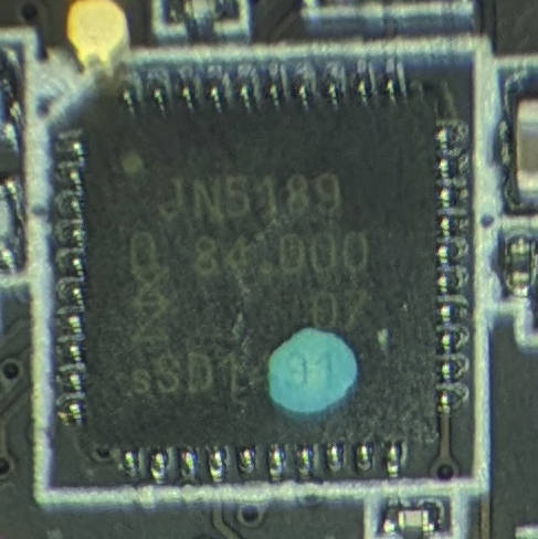
JN5189 MCU on the Aqara E1 light switch PCB
Disassembly revealed a JN5189 wireless MCU by NXP. This seemed like good news, as the JN5189 supports in-system programming (ISP) through the UART. Further investigation showed access to ISP via a set of pads conveniently located on the PCB.
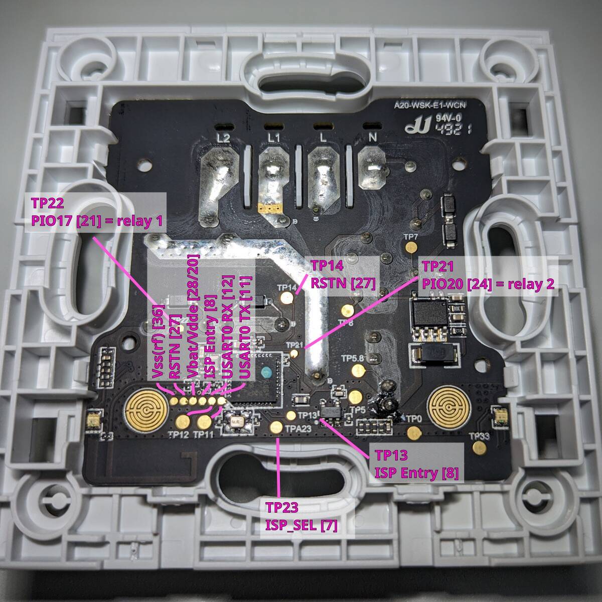
ISP pins on the Aqara E1 light switch PCB
JN5189 in-system programming
The device has a bootloader that provides programming via serial:
At boot time, the device can be placed in a mode where a USART is enabled and software commands can be sent into the device. These are serviced by the boot code and allow many operations to be performed, such as reading or writing memory, erasing the flash.
There is also functionality to protect the contents of devices from being accessed in certain configurations.
JN5189(T)/JN5188(T) UM11138 User Manual
The chip also includes functionality to lock down the ISP:
The ISP can be used at several levels of access:
- Unrestricted: normal developer mode
- Write-only: allows updates but existing contents cannot be read
- Locked: only allows limited access, with a secure handshake, for returns testing
Write-only would be fine, as I wasn’t looking to access the existing firmware, but locked would likely leave replacing the chip as the only option. Not necessarily a deal breaker, but close enough.
Confirming write access to the chip
The ISP protocol is explained in the user manual, but there’s no need to implement it as NXP provide a (Windows only) programming tool - the DK6Programmer.
I used a pogo pin clamp to connect a USB↔UART to the ISP pins, and left the reset_n and isp_sel pins on jumpers to trigger ISP entry manually:
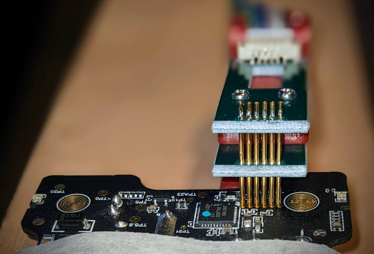
Pogo pin clamp connected to the ISP header on the PCB
After triggering ISP mode by holding isp_sel low during reset, I issued some DK6Programmer commands. I run Linux, but the software works without issue in a VM:
DK6Programmer successfully writes to target flash!
C:\nxp\DK6Programmer>DK6Programmer.exe --serial COM3 --nodevicereset --verbosity 2 --memory
  COM3: Connected at 115200
  COM3: Detected Unknown JN518x with MAC address 00:00:00:00:00:00:00:00
  COM3: Chip ID: 0x1140C686
  COM3: Bootloader Version: 0xCC000014
  COM3: Available memories: FLASH PSECT pFlash Config EFUSE ROM RAM0 RAM1


C:\nxp\DK6Programmer>DK6Programmer.exe --serial COM3 --verbosity 2 --erase
  COM3: Connected at 115200
  COM3: Detected Unknown JN518x with MAC address 00:00:00:00:00:00:00:00
  COM3: Chip ID: 0x1140C686
  COM3: Bootloader Version: 0xCC000014
  COM3: Selected memory: FLASH
  COM3: Erasing FLASH
  COM3: Full erase required on memory FLASH, addr=0x00000000, length=646656
  COM3: Erasing FLASH
  COM3: 0
  COM3: Completed
Bingo!
It was possible that if the ISP write didn’t work that an OTA update might still be have been possible, but this proved moot.
The outline of a plan
Confirm that the ISP write functionality is not locked🤞.✔- Reverse engineer the PCB to determine which GPIOs are used for the switches, relays, and indicator LEDs and how they are configured (i.e. active high/low, pullups etc.).
- Write new firmware that supports all of the desired features.
- Upload the new firmware to the device.
- Celebrate
What could be simpler. 😂😂😂
Next step - identifying the inputs and outputs.