
This is the fourth part of a five-part post detailing the design and implementation of new firmware for the Aqara E1 Zigbee light switches:
Sanity check - Blinky
For an initial sanity check, I modified the NXP SDK’s blinky example for the 4 LEDs of the Aqara QBKG41LM (DIO lines identified here) to make sure that it would accept and run new firmware.
const uint8_t NUM_LED = 4;
const uint32_t LED_LEFT_RED_PIN = 14;
const uint32_t LED_LEFT_BLUE_PIN = 13;
const uint32_t LED_RIGHT_RED_PIN = 7;
const uint32_t LED_RIGHT_BLUE_PIN = 6;

uint32_t pins[] = {
    LED_LEFT_RED_PIN,
    LED_RIGHT_RED_PIN,
    LED_LEFT_BLUE_PIN,
    LED_RIGHT_BLUE_PIN,
};

for (int i = 0; i < NUM_LED; i++) {
    LedInit(pins[i], 0);
    LedOff(pins[i]);
}

while (1)
{
    for (int i = 0; i < NUM_LED; i++) {
        for (int j = 0; j < (i+1); j++) {
            LedOn(pins[i]);
            SysTick_DelayTicks(150U);
            LedOff(pins[i]);
            SysTick_DelayTicks(150U);
        }
        SysTick_DelayTicks(500U);
     }
     SysTick_DelayTicks(1000U);
}
NXP Zigbee SDK - first impressions
Tolerable…in the context of MCU vendor provided SDKs
The SDK is tolerable, but contains a lot of what one might term “gotchas”. Problems you may not expect and that you can only learn through developing the samples, discovering them, and then determining their cause by inspecting the source. The initial period was painful, but once I became familiar with how things were structured, progressing became easier. More so than with the TI ZStack SDK.
On the plus side, everything is single threaded and runs in the same context, which simplifies debugging. On the other hand, a good chuck of the code is precompiled (including on-chip ROM) and without source. This latter issue is problematic when misconfiguration means that incoming messages never make it into the application or the accessible parts of the SDK, and there is no way to debug what is happening, or even determine that a message was received.
Not a tutorial
This article in not intended to provide an deep discussion of the SDK or development process. I wrote a separate article providing an introduction to development with the NXP Zigbee SDK here:
> Getting started with the NXP Zigbee SDK
Instead I’ll just highlight some challenging, novel, or particularly annoying aspects.
Where to start for the main firmware?
With a sample. The SDK includes the following two that seemed suitable:
JN-AN-1243
Base Device Behavior implementation for coordinator / router / end device.
JN-AN-1257
Window covering (i.e. Zigbee closure). This example shows step-by-step how to take JN-AN-1243 and add the functionality for a window covering endpoint.
I decided to base the application on JN-AN-1243, and add functionality from there, using JN-AN-1257 as a reference to understand the changes needed as endpoints and clusters are added.
These sample applications are available in the SDK package, which can be downloaded from the NXP site.
Implementing features
Momentary and toggle modes
The majority of switching requires a toggle action, where the target device is switched on and off alternately with each press. For some applications though, a momentary action can be desirable, such as holding down a button to raise a blind.
I implemented independent toggle/momentary settings for each tap combination. So 1-tap could toggle the local load, but 2-taps could open a blind while held, and 3-taps could close a bind while held for example.


Multi-tap and annoying delays
One annoyance with some devices that implement multi-tap is the delay between tapping the button and having the light turn on/command sent etc. The reason for this is clear - the device can’t know if you intend to continue tapping the button and so must wait several hundred milliseconds to see if you do.
You may have a two-button switch and only intend to use single-tap on the left button and single/double-tap on the right. In this scenario, it makes no sense for the device not to respond immediately to the first tap on the left button. Similarly the device shouldn’t wait for a third tap on the right button.
To deal with this, I implemented independent max_taps settings for each button. I also incorporated configurable max_time_between_taps, since some people are happy to hammer the button, while others may prefer a more leisurely tap sequence.
Device menus complicate the situation
I didn’t want to only rely on Zigbee2MQTT (i.e. writing ZCL attributes over the network) for configuration. For some settings (e.g max_time_between_taps), this is unavoidable, but for others, like max_taps, I wanted the ability to configure using the device buttons. Similarly, putting the device into the various possible binding modes should be possible locally.
To accomplish this, I created a menu system, whereby tapping the button n-times would enter the menu, which could then be navigated using taps and long presses. There are two menus: binding and device configuration, which require 4 and 5 consecutive taps to enter respectively. Additionally, there are two reset functions, which require 6 or 7-taps, with the final one being held.
This complicates the ability to remove the annoying delays mentioned above. The button may only ever by used to toggle the local load (i.e. max_taps = 1) and so it responds immediately on button down of the first tap, switching the load, but the device still needs to keep waiting to see if this is a 4/5/6/7-tap menu or reset combination.
This isn’t a problem in itself, but what should the device do when a second tap comes 300ms later? Is this the second tap in a 5-tap sequence to enter the configuration menu? Or is this the user wanting to turn off the light that they just turned on by mistake? We have two choices here:
- Toggle the output on every tap, which means switching the light on/off five times in quick succession even though the user is just trying to enter the menu.
- Toggle the output on the first tap only - i.e. wait
max_time_between_tapsbefore allowing a subsequent tap to switch the load
The downside of this second approach is that after turning the light on/off, you need to wait max_time_between_taps before you can toggle it again. The downside of the first option is obvious.
I initially chose the second option, but was frustrated by exactly the problem described. I found myself sometimes tapping the wrong button on a 2/3-button switch, and getting annoyed when an immediate subseqent tap did nothing. It felt sluggish. I then modified the code to use the first option, but only in situations where max_taps == 1. It feels like the correct approach given the infrequent use of menus/reset once everyhing is setup.
Squeezing multi-tap functionality into standard Zigbee binding
Two core features I wanted to include were:
- Multi-tap.
- The ability to do direct binding.
By default, the ZCL is not well setup to handle this combination. The on/off cluster, which is what is used by (non-dimming) lights and switches, has no concept of multi-tap. The only primary commands are on, off, and toggle.
Many devices that incorporate multi-tap update a cluster attribute with the latest event, report these changes to Zigbee2MQTT or HA, and rely on that software to trigger actions.
This is fine for setups with an always on hub like HA, but I prefer to bind things directly wherever possible.
The binding process
When devices are bound, two specific clusters are connected: one on a specific endpoint of each device. The clusters must be identical. So a light bulb that supports the On/off cluster as a server on one of its endpoints can only be bound with a device that has the On/off cluster as a client on one of its endpoints.
To differentiate between single, double, and triple taps, we need to use three different endpoints. To external devices, it will appear that there are three separate switches for each physical switch.
A lot of application endpoints are needed
| EP | Main clusters | Other clusters | |
|---|---|---|---|
| Application | |||
| 1/2/3 | Relay 1/2/3 | On/off (server) |
|
| 10/11/12 | Button 1/2/3 (single-tap) |
On/off (client) Window Covering(client) |
|
| 20/21/22 | Button 1/2/3 (double-tap) |
On/off (client) |
|
| 30/31/32 | Button 1 (triple-tap) |
On/off (client) |
|
| 100 | OTA / Config | OTA Update (client) Custom config. |
|
| Base | |||
| 242 | Green power | ||
| 0 | ZDO |
* Custom attributes
More flexible remote control through scripts
Binding is useful for simple switch -> light bulb type setups, but more flexibility is needed to control unrelated devices and also in determining specific ZCL commands. This is where software like Zigbee2MQTT and HA typically come in.
I wanted to take the firmware a bit further in that direction, and settled on allowing groups of preset ZCL commands to be sent on each switch/tap combination.
Setup is via Zigbee2MQTT, where for each single, double, or triple tap, one can enter a set of semi-colon delimited commands to be sent when that combination is tapped.
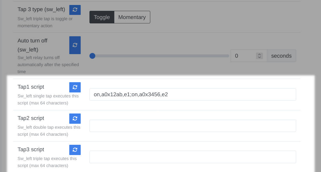
Script entry in Zigbee2MQTT
Calling them scripts is a bit of a stretch. There’s no program flow. They are just sequential commands. They are stored as string attributes in the on/off switch configuration cluster in each button endpoint.
I implemented the commands I most often used, and also a generic command to send any command/payload combination.
The full command list and syntax can be found in the firmware instructions (coming soon).
Fragmented messages
I had initially set the maximum length at 128-bytes, but this necessitated the use of fragmented messages to read/write them. Ths is because the maximum packet size on a Zigbee network is 127 bytes - a restriction of the 802.15.4 physical layer. 127-bytes is the maximum packet size, not payload size. By the time you add in the various headers for addressing, security, ZCL etc., you are left with about 65-70 bytes for the actual payload.
In principle fragmenting shouldn’t be a problem. The NXP stack can be configured to do it, but it proved relatively unreliable when I tried, and the higher level functions of the stack (report attribute etc.) are not setup for it and would need to be modified.
I’ll likely make the required changes and increase the limit at some point, but 64-bytes is sufficient for my current needs.
Reboot, factory reset, and emergency reset
Network reset versus factory reset
In the sample applications, and on other devices I’ve seen, leaving the network (either self initiated or via a command from the coordinator) typically resets all persistent settings.
With so many configurable parameters, including script commands, this didn’t seem like the right approach here. The Zigbee spec only requires the Zigbee-related persistent data to be cleared, although it does sort of imply that the configuration should also be reset:
…and perform a reset such that the node is in much the same state as it was when it left the factory.
Zigbee Base Device Behavior Specification
There’s a lot of room in “much the same”.
I decided to keep the local configuration on a network leave/reset and only clear it during a locally initiated factory reset.
The local configuration is the group of settings configurable in the Zigbee2MQTT exposes tab, or via the device configuration menu (max taps, button timing, LED color etc.). All network settings such as the routing table, binding table etc. are cleared in all scenarios.
Factory reset
Factory reset is executed by tapping the left-most (or only) button 7 times, but keeping it held on the seventh tap. The device then enters a reset countdown, with the device LEDs all flashing red. The frequency of flashing increases over 10 seconds until it is solid and the device performs a factory reset. Releasing the button at any time prior to the reset aborts it. All persistent settings are removed and the configuration is restored to its default state.
Backup emergency factory reset method
I was concerned that an unforseen bug could result in some specific state preventing the device resetting via the 7-tap sequence described above. In such a scenario, it may be impossible to recover without ISP access. To counter this possibility, I implemented a reset-at-power-up-via-button-hold function. This is a full factory reset identical to the 7-tap factory reset.
The code for this doesn’t rely on the button state machine, interrupts etc., and runs very early in the bootup process, with a simple GPIO check to see if the button is held and the hold timer using a busy spin rather than the systick interrupt.
Simple reboot
The device only searches for a new network to join for 30-seconds on startup. In situations where you wish to restart the search, but not factory reset the device (i.e. wish to keep prior settings), this reboot is available. The process is the same as the 7-tap factory reset, except the button is held on the 6th tap, not the 7th, and the LEDs flash blue.
Device configuration through ZCL attributes
The relays do not require any configuration*. They are on/off server endpoints, and are always available to be controlled remotely via binding, scenes, normal on/off commands from the coordinator or other devices, etc.
The buttons on the other hand must be configurable to achieve maximum flexibility, such as selecting the toggle/momentary mode discussed above or choosing which relay to switch when the button is tapped. There are also various configuration options that are not button specific, such as LED output, OTA settings and the like.
I wanted to provide some configuration capability via the device itself (menus accessed via button press combinations), but Zigbee2MQTT was intended to be the main UI for adjusting settings. The settings therefore needed to be ZCL attributes.
* Aside from the configurable off timer.
Extending the on/off switch config cluster
Since there is already a standard ZCL On/off switch config cluster (OOSC - 0x0006) , I extended it with the following additional custom attributes:
OOSC cluster custom attributes
| Attribute | ID | type | def. | min | max | |
|---|---|---|---|---|---|---|
| MAX_TAPS | 0xf000 |
uint8 | 1 | 1 | 3 | taps |
| TAP_1_SWITCHES_RELAY | 0xf001 |
enum8 | 1 | 0 | #channels + 1 | 0 = none 1 = left … #channels + 1 = all |
| TAP_2_SWITCHES_RELAY | 0xf002 |
enum8 | 0 | 0 | #channels + 1 | 0 = none 1 = left … #channels + 1 = all |
| TAP_3_SWITCHES_RELAY | 0xf003 |
enum8 | 0 | 0 | #channels + 1 | 0 = none 1 = left … #channels + 1 = all |
| TAP_1_IS_MOMENTARY | 0xf004 |
bool | 0 | 0 | 1 | 0 = toggle 1 = momentary |
| TAP_2_IS_MOMENTARY | 0xf005 |
bool | 0 | 0 | 1 | 0 = toggle 1 = momentary |
| TAP_3_IS_MOMENTARY | 0xf006 |
bool | 0 | 0 | 1 | 0 = toggle 1 = momentary |
| TURN_OFF_AFTER_N_SEC | 0xf007 |
uint16 | 0 | 0 | 50000 | seconds (0 = disabled) |
| TAP_1_SCRIPT | 0xf008 |
cstring | "" | 0..64-char string | ||
| TAP_2_SCRIPT | 0xf009 |
cstring | "" | 0..64-char string | ||
| TAP_3_SCRIPT | 0xf00a |
cstring | "" | 0..64-char string |
A new device config cluster
For switch-wide settings, I created a new custom device configuration cluster:
Custom configuration cluster (0xfc01) attributes
| Attribute | ID | type | def. | min | max | |
|---|---|---|---|---|---|---|
| MAX_TIME_BETWEEN_TAPS_MS | 0xf000 |
uint16 | 500 | 100 | 2000 | milliseconds |
| MIN_TIME_FOR_HOLD_MS | 0xf001 |
uint16 | 1100 | 50 | 2000 | milliseconds |
| ONOFF_LED_TYPE | 0xf002 |
uint8 | 1 | 0 | 2 | 0 = disabled 1 = on when on 2 = on when off |
| ONOFF_LED_COLOR | 0xf003 |
uint8 | 1 | 0 | 1 | 0 = red 1 = blue |
| OTA_BLOCK_DELAY_MS | 0xf004 |
uint16 | 250 | 50 | 10000 | milliseconds |
| SHOW_ERR_LED_ON_NO_COORD | 0xf005 |
bool | 0 | 0 | 1 | binary |
And a final status cluster
Finally, I added an additional custom status cluster to output status information:
Custom status cluster (0xfc02) attributes
| Attribute | ID | type | |
|---|---|---|---|
| UPTIME | 0xf000 |
uint32 | days |
| STATUS | 0xf001 |
cstring | last error description |
Full details of the application endpoints, clusters, etc. can be found in the technical details readme.
Zigbee2MQTT
Button actions
All button actions are sent to the coordinator. They are reported as value changes of the PresentValue attribute (0x0055) of the MultistateInput cluster (0x0012) on the single-tap endpoint for that button.
Coordinator software such as Zigbee2MQTT will report these actions via MQTT allowing for external software to react as required.
The switch events are:
0 tap_1_tap
1 tap_2_tap
2 tap_3_tap
3 tap_1_hold
4 tap_2_hold
5 tap_3_hold
6 tap_1_release
7 tap_2_release
8 tap_3_release
Note that for a specific number of taps, either tap_x_tap or tap_x_hold/tap_x_release will be reported, depending on the switch configuration for that number of taps.
External converter
Zigbee2MQTT features a very flexible extension system, allowing for non-standard ZCL clusters, commands, and attributes to be exposed via “converters”.
I ran into a couple of issues that needed patching to getting things working fully, but nothing major.
OTA updates
Although it was likely going to be necessary to upload the initial firmware via ISP, ongoing updates should use the OTA mechanism. Getting OTA update working took longer than expected. I wrote a separate article here:
> Zigbee2MQTT, the NXP Zigbee stack, and OTA updates
Possible future additions
Notifications
The idea of using light switch LEDs indicators as visual outputs for the broader smart home seems interesting. I can imagine scenarios like flashing all switches red during some emergency condition such as a water overflow sensor triggering, or overheating in a switch, or flashing some sequence when rain is expected etc.
The ZCL is not really setup for this. There’s the digital output cluster, and the usual on/off/color control etc., but they’re not really designed for visual status output. The alarms cluster is probably more suitable. Local configuration could set alarm 1 = flash red slowly, alarm 2 = flash red then blue etc.
Longer (fragmented) scripts
As described above, “scripts” are currently limited to 64-bytes. This may be increased in future using fragmented messages.